21
21
21
21
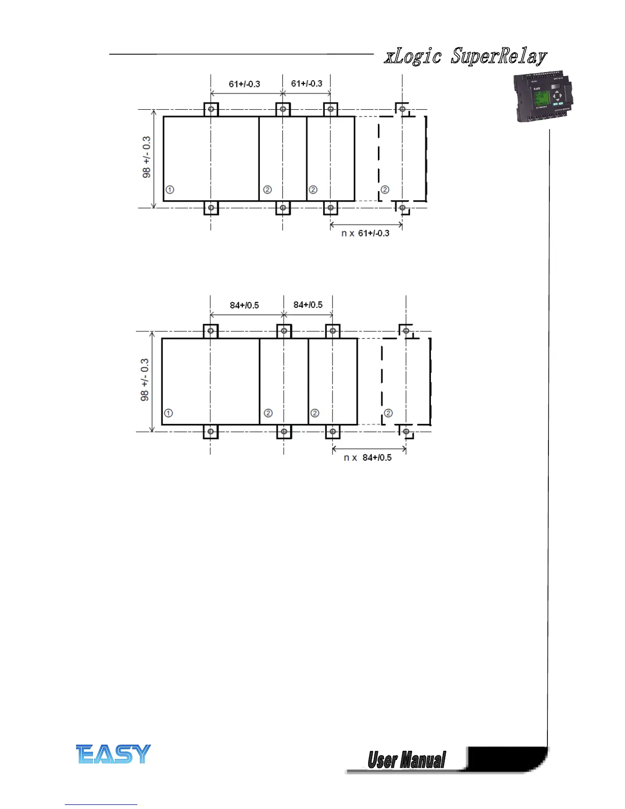
ELC-18
ELC-18
ELC-18
ELC-18 series:
series:
series:
series:
All dimensions in mm
Bore hole for Ø M4 screw, tightening torque 0.8 to 1.2 Nm
1. xLogic CPU
2. xLogic extensions
2.1.3
2.1.3
2.1.3
2.1.3 Mouting
Mouting
Mouting
Mouting ELC-HMI-FP
ELC-HMI-FP
ELC-HMI-FP
ELC-HMI-FP
ELC-HMI-FP
ELC-HMI-FP
ELC-HMI-FP
ELC-HMI-FP , Faceplate ( ELC-HMI
’
s installation unit), making it possible for ELC-HMI to be
externally installed in the front door of cabinet for easy observation and operation while
ELC-12 CPU is required to be installed inside.
To prepare the mounting surface for the optional ELC-HMI-FP
ELC-HMI-FP
ELC-HMI-FP
ELC-HMI-FP TD and mount it, follow these
steps: