EasyManua.ls Logo

Easy xLogic User Manual

Easy xLogic
226 pages
To Next Page IconTo Next Page
To Previous Page IconTo Previous Page
Page #49 background imageLoading...
Page #49 background image
47
47
47
47
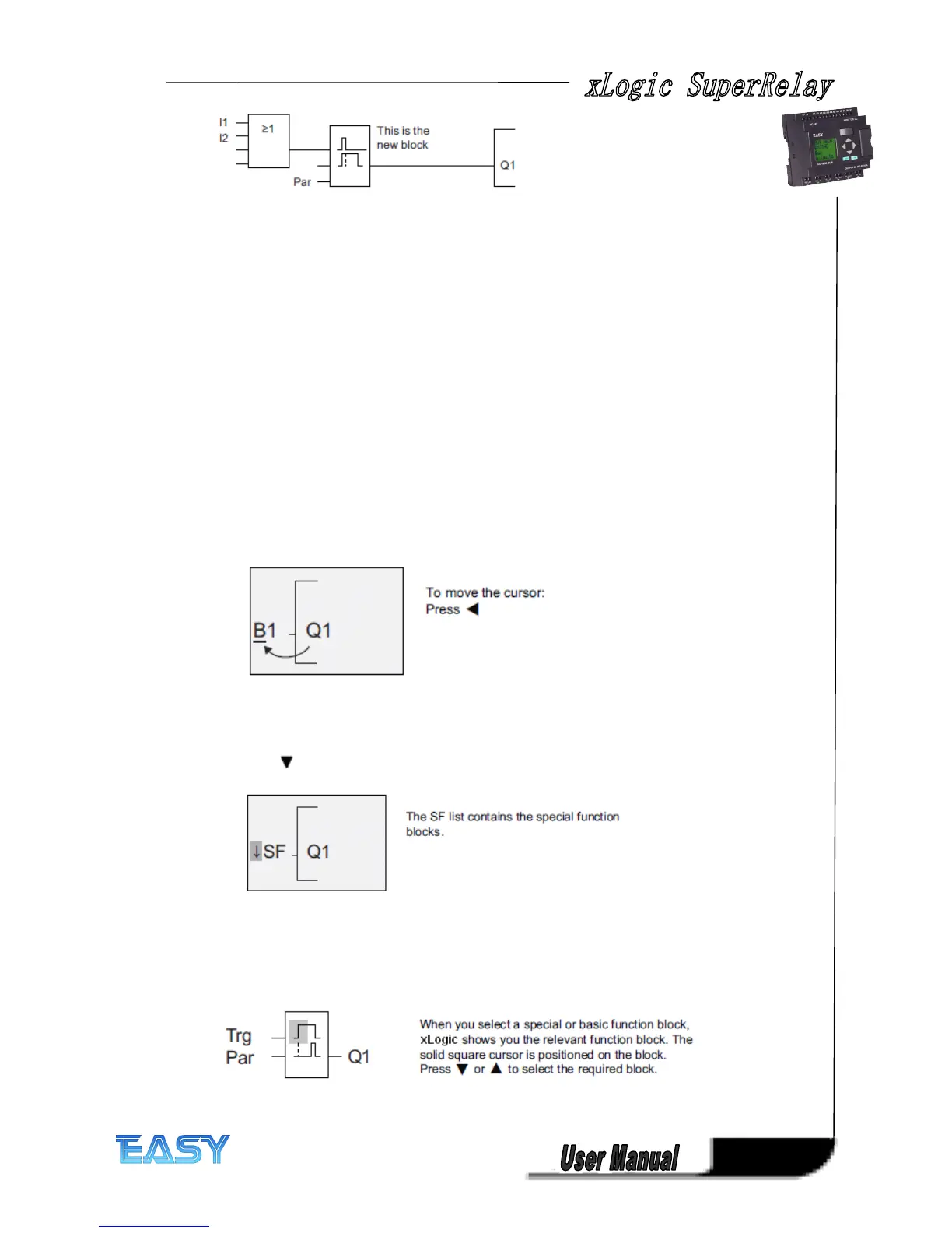
You can see the OR block and the output relay Q1 we have already used in the first circuit
program. The only difference is the new off-delay block.
Editing
Editing
Editing
Editing the
the
the
the circuit
circuit
circuit
circuit program
program
program
program
Switch xLogic to programming mode.
As a reminder:
1. Switch xLogic to programming mode
(in RUN: Press ESC to enter the parameter assignment mode. Select the 'Stop' command,
confirm with OK, then move the '>' cursor to 'Yes', and once again confirm with OK). For
additional details, see the topic "The four golden rules for operating xLogic ".
2. On the main menu, select "Program"
3. On the Programming menu, select "Edit", confirm with OK. Next, select "Edit Prg" and
confirm with OK.If required, enter your password at the prompt and confirm with OK. You can
now modify the current circuit program.
Adding
Adding
Adding
Adding a
a
a
a block
block
block
block to
to
to
to a
a
a
a circuit
circuit
circuit
circuit program
program
program
program
Move the cursor to the B in B1 (B1 is the number of the OR block):
We now insert the new block at this position.
Confirm with OK.
Press to select the SF list:
Press OK.
The block of the first special function is shown:
Select your block (off-delay, see the next figure), and then press OK:
Question and Answer IconNeed help?

Do you have a question about the Easy xLogic and is the answer not in the manual?

Easy xLogic Specifications

General IconGeneral
Number of digital inputs8
Protection classIP20
Input voltage range24 V DC
Operating temperature range-25°C to +55°C
Storage temperature range-40°C to +70°C

Summary

Chapter 1 General Introduction to xLogic

Overview

Describes the xLogic SuperRelay as a universal logic module replacing PLCs, timers, relays.

Highlight Features

Lists key features like display, keypad programming, function block diagram, and communication protocols.

Communication modules

Explains various communication modules like RS232, USB, Ethernet, and SMS for connectivity.

Naming Rules of ELC Series

Model name (main module)

Explains the naming convention for ELC series main modules, detailing each component.

Model name (expansion module)

Details the naming convention for ELC-18 and ELC-12 CPU expansion modules.

Chapter 2 Installing/removing xLogic

Structure

Illustrates the structure and component identification of ELC-18 and ELC-12 Series CPUs.

DIN rail mounting

Step-by-step guide for mounting xLogic modules onto a DIN rail.

Wall-mounting

Instructions for wall-mounting xLogic devices using mounting slides and screws.

2.2 Wiring the xLogic

Connecting the power supply

Details power supply requirements for AC and DC versions of xLogic modules.

Connecting xLogic Inputs

Explains connecting sensor elements to xLogic inputs, including analog and digital.

Connecting xLogic Outputs

Describes connecting loads to relay and transistor outputs, including current limits.

Chapter 3 Programming xLogic

Getting started with xLogic

Introduces creating circuit programs for xLogic applications using xLogicSoft or directly on the unit.

The four golden rules for operating xLogic

Outlines four key rules: changing mode, inputs/outputs, cursor movement, and planning.

Writing and starting the circuit program

Guides on how to write a designed circuit program into the xLogic unit.

Chapter 4 xLogic functions

General Input & Output functions

Introduces input and output blocks, describing their role in xLogic programs.

Basic functions list – GF

Lists simple logical elements like AND, NAND, OR, NOR, XOR, NOT used in circuit programs.

Special functions list – SF

Lists available special function blocks (Timers, Counters, Analog, Miscellaneous) with their functions.

Modbus Read

Covers activating Modbus Read for communication as a master via RS232/RS485.

PI controller

Describes Proportional-integral controllers for controlling processes.

Chapter 5. Configuring xLogic

Instruction of xLogic-HMI

Guides on the initial screen display and navigation for xLogic HMI.

Set parameter

Guides on selecting and modifying parameters for function blocks.

Set password

Provides instructions for setting, modifying, and removing passwords for program protection.

Chapter 6. Application

Dual-function switch

Discusses requirements for stairway lighting systems and control methods.

Automatic gate

Covers automatic gate applications in supermarkets, buildings, etc., and their requirements.

Ventilation system

Details ventilation systems supplying fresh air and exhausting contaminated air, with sample system requirements.

Chapter 7 xLogic Software

xLogicsoft features

Lists features of xLogicsoft: graphic interface, simulation, printing, saving, configuration, transfer, online test.

Installing xLogicsoft(xLogic)

Step-by-step guide for installing xLogicsoft, including language selection and license agreement.

Program Testing

Explains testing the program, modifying parameters, and comparing calculations with actual behavior.

Appendix A Technical data

General technical data

Provides technical specifications for ELC-18/12 Series Main Modules and Expansion Modules.

Technical data: xLogic (ELC series)

Provides detailed technical specifications for ELC-6, ELC-12, and ELC-18 series CPU units.

Switching capacity and service life of the relay outputs

Illustrates switching capacity and service life curves for ohmic and inductive loads.

Related product manuals