124
124
124
124
Note:
Note:
Note:
Note:
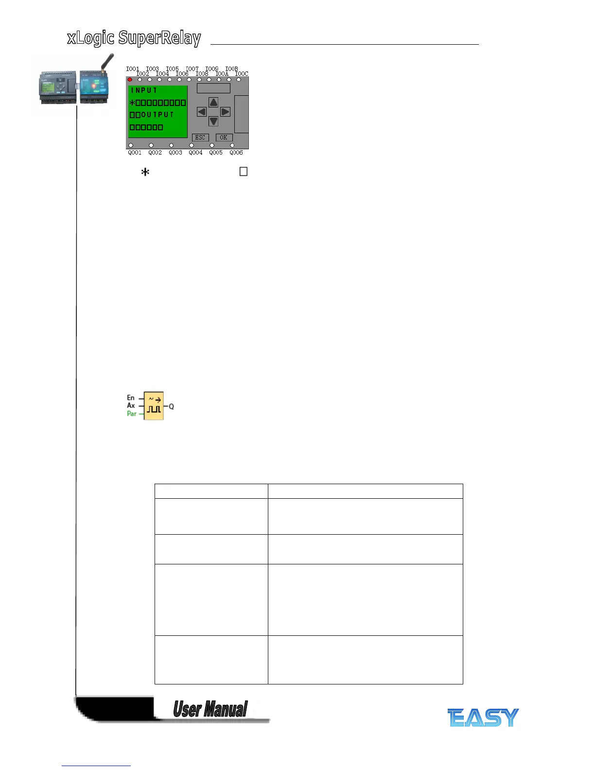
represents high pulse, represents low pulse.
Description
Description
Description
Description of
of
of
of the
the
the
the priority
priority
priority
priority of
of
of
of HMI
HMI
HMI
HMI blocks:
blocks:
blocks:
blocks:
If several HMI blocks are placed in the program, the messages in the respective block would be
displayed according to priority level (1 = lowest, 32 = highest). After a message is disabled or
acknowledged, the function automatically shows the previously active message text that takes
the highest priority, but you can change the human machine interface via press the Left and
Right key.
Note:
Note:
Note:
Note: IO status can be viewed by click “ left ” or “ right ” button after the “ system IO ” block had
put in your program.
4.6
4.6
4.6
4.6 Pulse
Pulse
Pulse
Pulse Width
Width
Width
Width Modulator
Modulator
Modulator
Modulator (PWM)
(PWM)
(PWM)
(PWM)
S
S
S
S hort
hort
hort
hort D
D
D
D escription
escription
escription
escription :
:
:
:
The Pulse Width Modulator (PWM) instruction modulates the analog input value Ax to a pulsed
digital output signal. The pulse width is proportional to the analog value Ax.
connection
connection
connection
connection D
D
D
D escription
escription
escription
escription
EN
EN
EN
EN A positive edge (0 to 1 transition) at
input En enables the PWM function
block.
I nput Ax
Ax
Ax
Ax Analog signal to be modulated to a
pulsed digital output signal.
parameter
parameter
parameter
parameter
A:
A:
A:
A: Gain
Range of values: +- 10.00
B:
B:
B:
B: Zero offset
Range of values: +- 10,000
PT:
PT:
PT:
PT: Periodic time over which the
digital output is modulated
p:
p:
p:
p: Number of decimals
Range of values: 0, 1, 2, 3
Output Q
Q
Q
Q Q is set or reset for the proportion of each time
period according to the proportion of the
standardized value Ax to the analog value range.