28
28
28
28
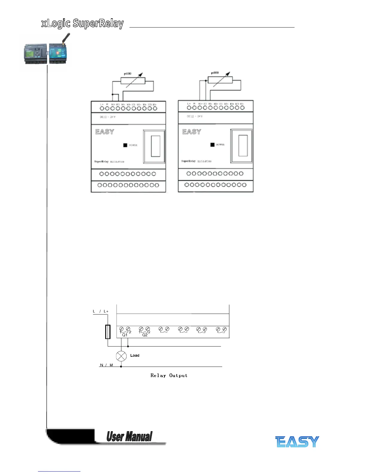
Two-wire technology three-wire technology
2.2.3
2.2.3
2.2.3
2.2.3 Connecting
Connecting
Connecting
Connecting xLogic
xLogic
xLogic
xLogic Outputs
Outputs
Outputs
Outputs
1.
1.
1.
1. Requirement
Requirement
Requirement
Requirement for
for
for
for the
the
the
the relay
relay
relay
relay output
output
output
output
Various loads such as lamp, fluorescent tube, motor, contact, etc., can be connected to the
outputs of xLogic. The maximum ON output current that can be supplied by xLogic is 10A for
the resistance load and 2A for the inductive load. The connection is in accordance with the
following figure:
2.
2.
2.
2. Requirement
Requirement
Requirement
Requirement for
for
for
for the
the
the
the electronic
electronic
electronic
electronic transistor
transistor
transistor
transistor output:
output:
output:
output:
The load connected to xLogic must have the following characteristics:
*
*
*
* The maximum switch current cannot exceed 2A.
*
*
*
* When the switch is ON (Q=1), the maximum current is 2A.