18
18
18
18
C
C
C
C hapter
hapter
hapter
hapter 2
2
2
2 Installing/removing
Installing/removing
Installing/removing
Installing/removing xLogic
xLogic
xLogic
xLogic
Dimensions
Dimensions
Dimensions
Dimensions
The xLogic installation dimensions are compliant with DIN 43880.
xLogic can be snap-mounted to 35 mm DIN rails to EN 50022 or on the wall.
xLogic width:
ELC-12 Series Main Module has a width of 72mm.
ELC12-E expansion mddule have a width of 48mm
ELC-18 Series Main Module has a width of 95mm.
�
�
�
�
ELC-E expansion modules have a width of 72 mm .
Note
Note
Note
Note
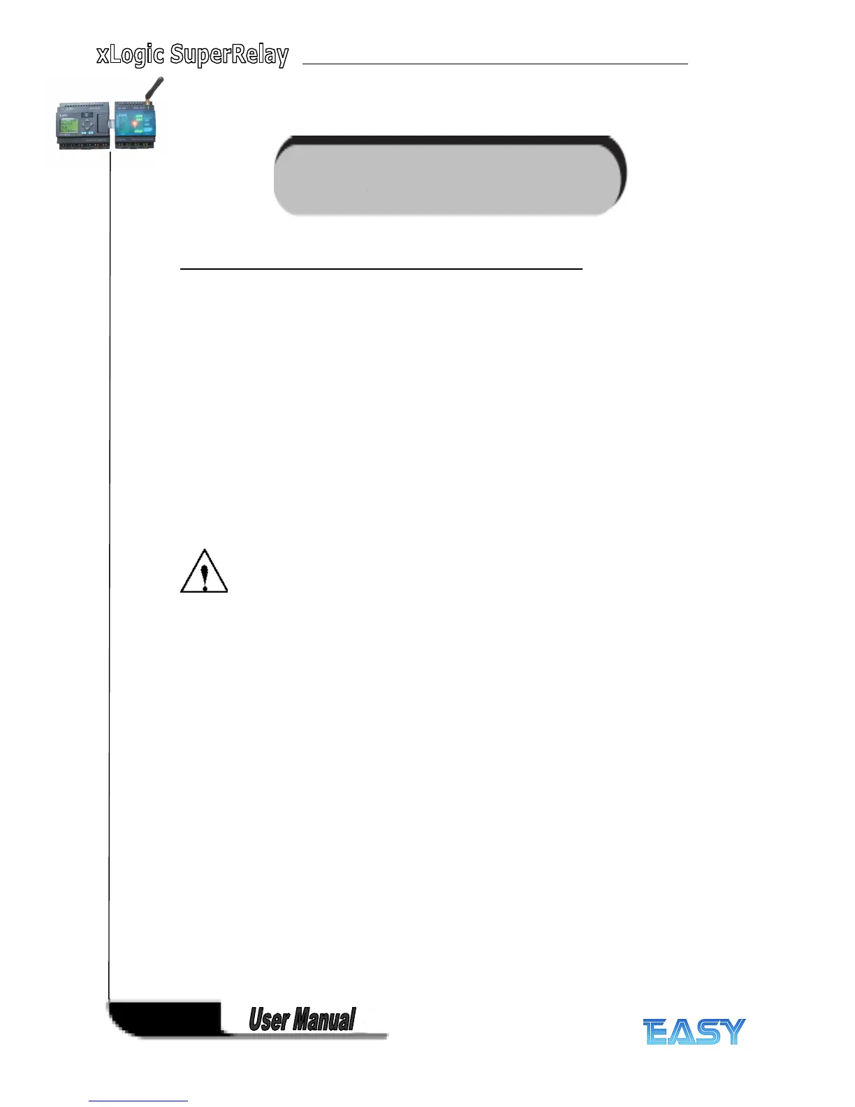
The figure below shows you an example of the installation and removal of an ELC-12 CPU and
one expansion module ELC-12 CPU . The measures shown apply to all other ELC-12 Series
versions and ELC-18 Series versions and expansion modules.
Warning
Warning
Warning
Warning
Always switch
off
power before
you
“
remove
” and
“
insert
” an expansion module.
2.1
2.1
2.1
2.1 .1
.1
.1
.1 DIN
DIN
DIN
DIN rail
rail
rail
rail mounting
mounting
mounting
mounting
Mounting
Mounting
Mounting
Mounting
How to mount a xLogic Basic module and a expansion module onto a DIN rail:
1. Hook the xLogic Basic module onto the rail.
2. Push down the lower end to snap it on. The mounting interlock at the rear must engage.
3. Hook the xLogic expansion m odule onto the rail
4. Slide the digital module towards the left until it contacts the xLogic Basic.
5. Push down the lower end to snap it on. The mounting interlock at the rear must engage.
6. Take the plastic cover in the expansion port of CPU and expansion module.
7 . Plus the connection bridge