78
78
78
78
The off-delay time T, the prewarning time T! and the prewarning period T!L can be provided by
the actual value of another already-programmed function:
Analog comparator: Ax – Ay
Analog trigger: Ax
Analog amplifier: Ax
Analog multiplexer: AQ
Analog ramp: AQ
Analog math: AQ
PI controller:AQ
Data latching relay: AQ
Up/Down counter: Cnt
The value of "T" can be set/modified in parameter mode. For information about how to
modify, refer to chapter 5 .2.2 please.
Timing
Timing
Timing
Timing diagram
diagram
diagram
diagram
Changing
Changing
Changing
Changing the
the
the
the time
time
time
time base
base
base
base
You can change the pre - warning time base and the period.
Description
Description
Description
Description of
of
of
of the
the
the
the function
function
function
function
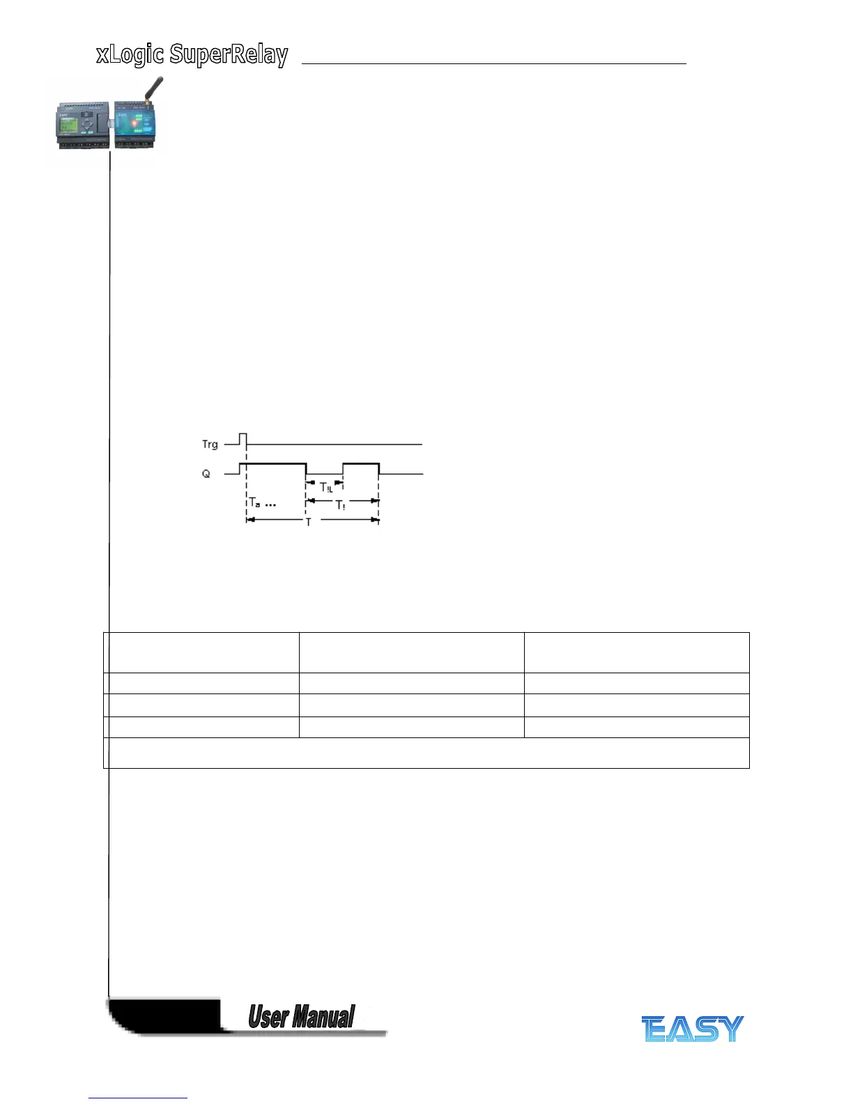
Output Q is set to 1 with a 0 to 1 signal transition at input Trg. The 1 to 0 transition at input Trg
triggers the current time and output Q remains set.
Output Q is reset to 0 when Ta reaches the time T. Before the off delay time (T - T
!
) has expired,
you can output a pre - warning that resets Q for the duration of the off pre - warning time T
!L
.
Ta is retriggered (optional) at the next high/low transition at input Trg and if Ta is expiring.
If retentivity is not set, output Q and the expired time are reset after a power failure.
Setting
Setting
Setting
Setting the
the
the
the Par
Par
Par
Par parameter
parameter
parameter
parameter
Note
All times must have the same timebase.
Time
Time
Time
Time
base
base
base
base
T
T
T
T
Pre
Pre
Pre
Pre -
-
-
- warning
warning
warning
warning
time
time
time
time
Pre
Pre
Pre
Pre -
-
-
- warning
warning
warning
warning
period
period
period
period
Seconds 750 ms 50 ms
Minutes 15 s 1 s
Hours 15 min 1 min
* makes sense only for programs with a cycle time of < 25 ms