94
94
94
94
The gate time G_T can be provided by the actual value of another already-programmed
function:
Analog comparator: Ax – Ay
Analog trigger: Ax
Analog amplifier: Ax
Analog multiplexer: AQ
Analog ramp: AQ
PI controller:AQ
Up/Down counter: Cnt
Data latching relay: AQ
Analog Math AQ
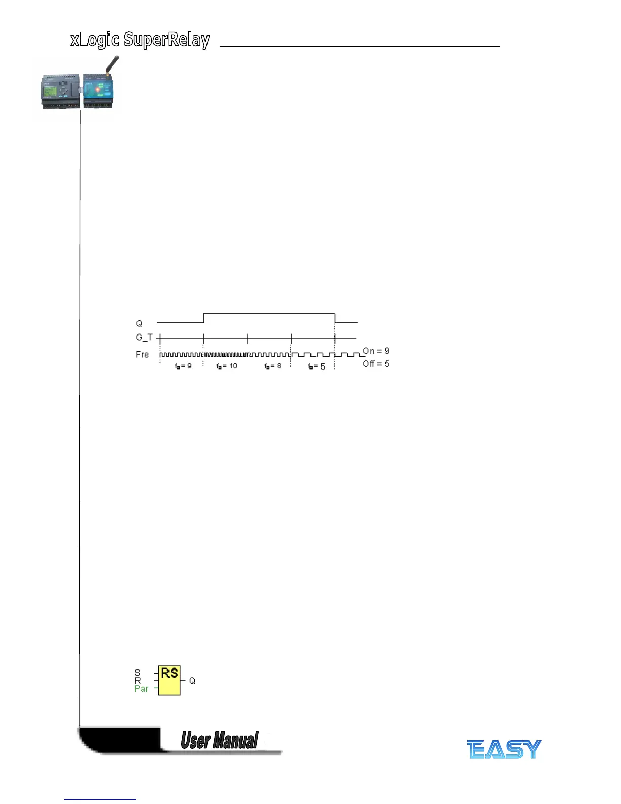
The value of " On " , " Off " can be set/modified in parameter mode. For information about how
to modify, refer to chapter 5 .2.2 please.
Timing
Timing
Timing
Timing diagram
diagram
diagram
diagram
fa = Input frequency
Description
Description
Description
Description of
of
of
of the
the
the
the function
function
function
function
The trigger measures the signals at input Fre. The pulses are captured during a configurable
period G_T.
Q is set or reset according to the set thresholds. See the following calculation rule.
Calculation
Calculation
Calculation
Calculation rule
rule
rule
rule
• If the threshold (On) > threshold (Off), then:
Q = 1, if fa >= On
Q = 0, if fa < Off.
• If the threshold (On) < threshold (Off), then Q = 1, if
On <= fa < Off.
4
4
4
4 .4.16
.4.16
.4.16
.4.16 Latching
Latching
Latching
Latching relay
relay
relay
relay
Short
Short
Short
Short description
description
description
description
A signal at input S sets output Q. A signal at input R resets output Q.