Installation
Eaton 9130 700/3000 VA UPS User’s Guide 164201718—Rev 7 www.eaton.com/powerquality 18
3. If you are installing EBMs, see the following section, “Connecting the EBM(s),” before continuing with the
UPS installation.
4. Replace the UPS right front cover.
To replace the cover, verify that the ribbon cable is p
rotected and (if EBMs are installed) the EBM cable is
routed through the knockout on the bottom of the cover. Slide the cover to the left until it aligns with the
left front cover. Reinstall the two screws on the right side of the right front cover.
5. If you are installing power management software, connect your computer to one of the communication
ports or optio
nal connectivity card (see page 39 and page 39). For the communication ports, use an
appropriate cable (not supplied).
6. If your rack has conductors for grounding or bonding
of ungrounded metal parts, connect the ground cable
(not supplied) to the ground bonding screw. See “Rear Panels” on page 69 for the location of the ground
bonding screw for each model.
7. If an emergency power-off (disconnect) switch is required by local codes, see “Remote Emergency
P
ower-off” (REPO) on page 40 to install the REPO switch before powering on the UPS.
8. Continue to “UPS Initial Startup” on page 24.
Connecting the EBM(s)
To install the optional EBM(s) for a UPS:
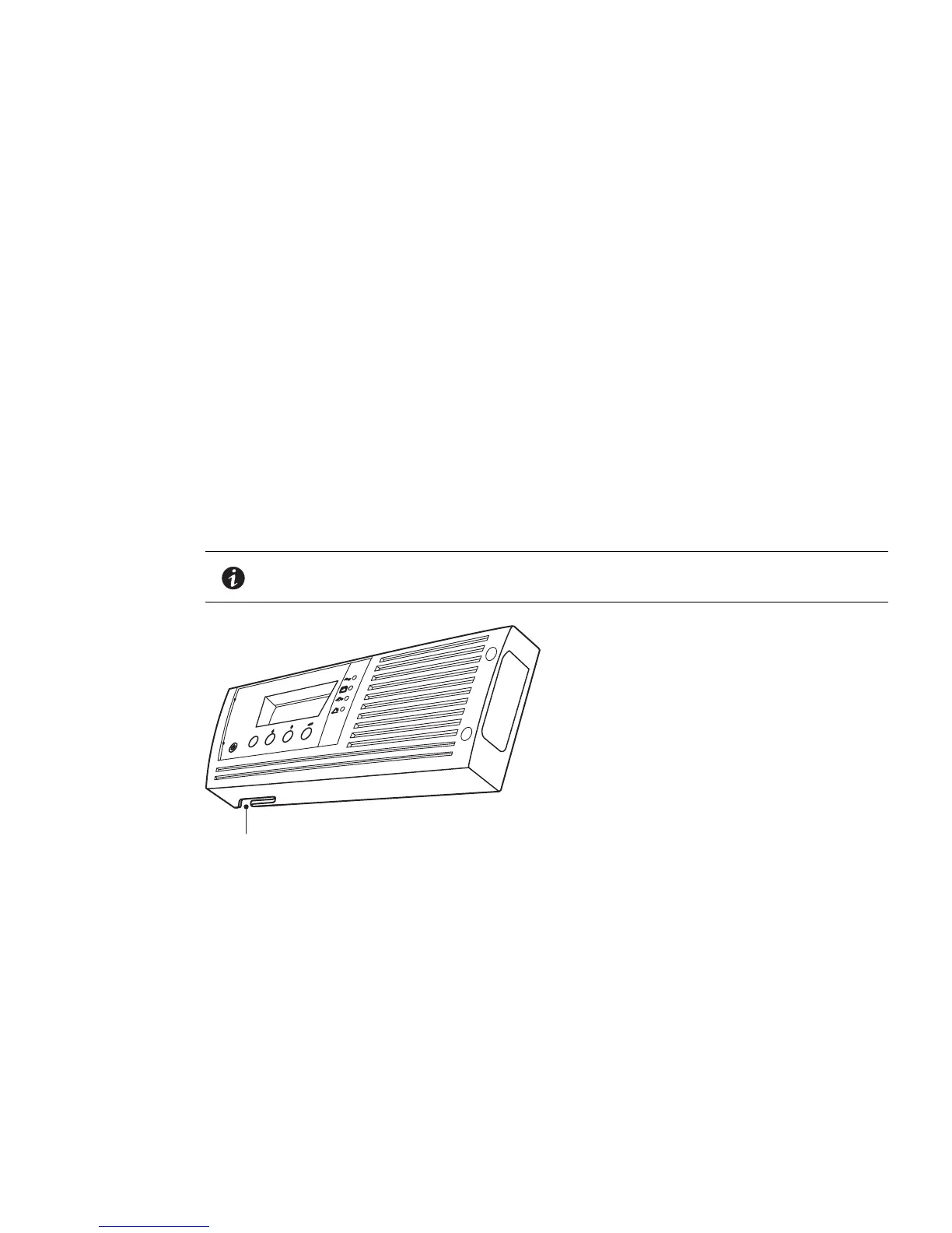
1. On the bottom of the UPS right front cover, remove the EBM cable knockout (see Figure 11).
NOTE Use care to protect the LCD control panel and the connected ribbon cable from
damage.
esc
Knockout for EBM Cable
Figure 11. Removing the EBM Cable Knockout
2. Remove the front cover of each EBM (see Figure 12).
To remove the cover, remove and retain the two screws o
n the right side of the cover. Grasp the sides of
the cover and slide the cover to the left and then away from the cabinet.