Installation
Eaton 9130 700/3000 VA UPS User’s Guide 164201718—Rev 7 www.eaton.com/powerquality 22
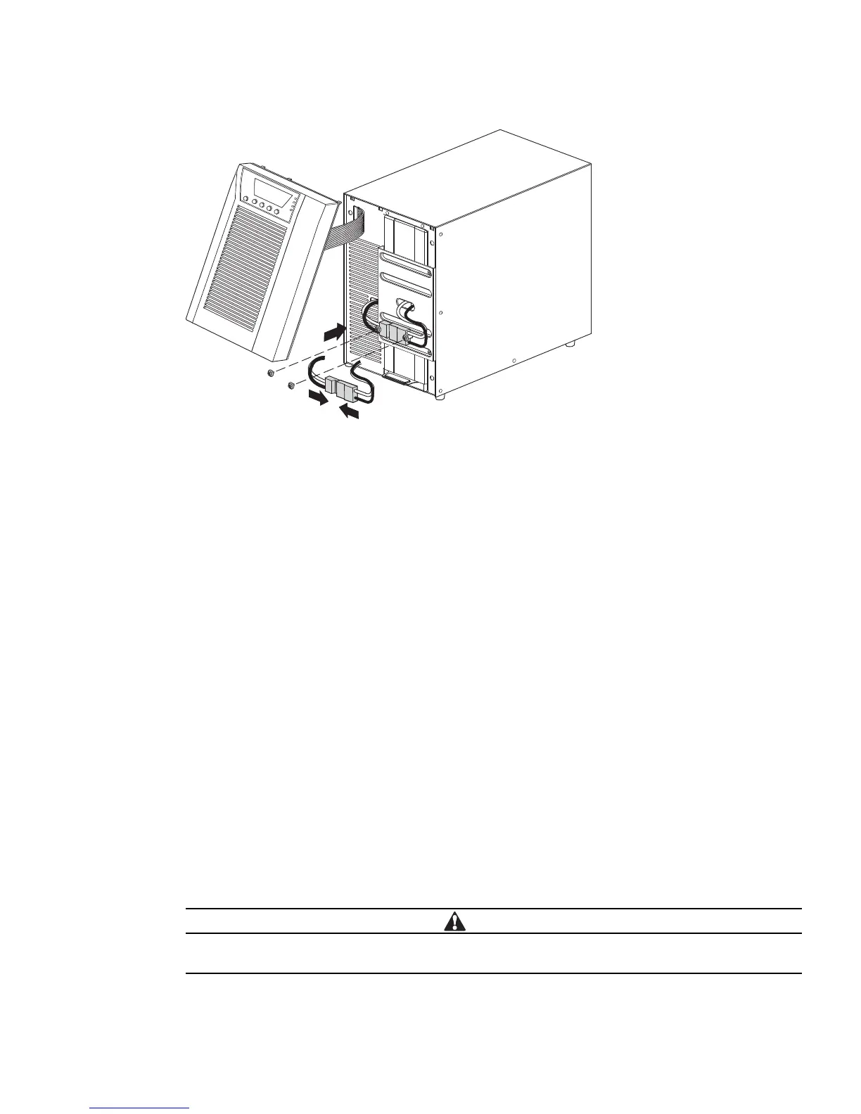
Figure 15. Connecting the UPS Internal Batteries
3. Remove the two screws from the screw mounts and retain (see Figure 15).
4. Place the battery connector between the screw mounts. Reinstall the two screws to hold the connector
in pl
ace.
5. Replace the UPS front cover.
To replace the cover, verify that the ribbon cable is protected
, then insert the clips on the back of the cover
into the cabinet and push firmly to snap the cover into place.
6. If you are installing power management software, connect your computer to one of the communication
ports or optio
nal connectivity card (see page 39 and page 39). For the communication ports, use an
appropriate cable (not supplied).
7. If an emergency power-off (disconnect) switch is required by local codes, see “Remote Emergency
P
ower-off” (REPO) on page 40 to install the REPO switch before powering on the UPS.
8. If you are installing EBM(s), continue to the followin
g section, “Connecting the EBM(s).” Otherwise,
continue to “UPS Initial Startup” on page 24.
Connecting the EBM(s)
To install the optional EBM(s) for a UPS:
1. On the rear of the UPS, remove the cable retention clip covering the battery connector. Retain the clip and
scre
ws. See Figure 16.
2. In
stallations with one EBM only. Remove the cable retention clip covering the right (for 1000–1500 VA
models) or upper (for 2000–3000 VA models) battery connector. Retain the clip and screws.
3. In
stallations with more than one EBM. For all EBMs except the last EBM, remove the cable retention
clips covering both battery connectors. Do not remove the clip from the second battery connector on the
last EBM. Retain the clips and screws.
A small amount of arcing may occur when connecting an EBM to the UPS. This is normal and will
not harm personnel. Insert the EBM cable into the UPS battery connector quickly and firmly.