Page 7
614-09354-01_EN
ENGLISH
2. Presentation
2.2 Description / Panels
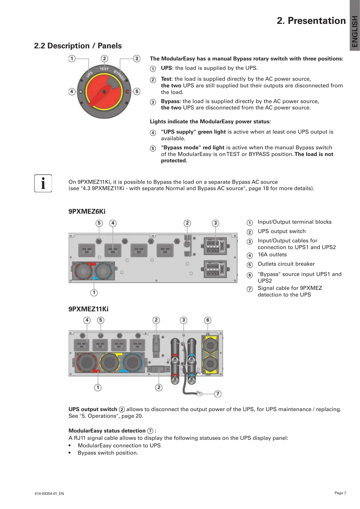
The ModularEasy has a manual Bypass rotary switch with three positions:
1
UPS: the load is supplied by the UPS.
2
Test: the load is supplied directly by the AC power source,
the two UPS are still supplied but their outputs are disconnected from
the load.
3
Bypass: the load is supplied directly by the AC power source,
the two UPS are disconnected from the AC power source.
Lights indicate the ModularEasy power status:
4
"UPS supply" green light is active when at least one UPS output is
available.
5
"Bypass mode" red light is active when the manual Bypass switch
of the ModularEasy is on TEST or BYPASS position. The load is not
protected.
On 9PXMEZ11Ki, it is possible to Bypass the load on a separate Bypass AC source
(see "4.3 9PXMEZ11Ki - with separate Normal and Bypass AC source", page 18 for more details).
9PXMEZ6Ki
1
Input/Output terminal blocks
2
UPS output switch
3
Input/Output cables for
connection to UPS1 and UPS2
4
16A outlets
5
Outlets circuit breaker
6
"Bypass" source input UPS1 and
UPS2
7
Signal cable for 9PXMEZ
detection to the UPS
9PXMEZ11Ki
UPS output switch
2
allows to disconnect the output power of the UPS, for UPS maintenance / replacing.
See "5. Operations", page 20.
ModularEasy status detection
7
:
A RJ11 signal cable allows to display the following statuses on the UPS display panel:
• ModularEasyconnectiontoUPS
• Bypassswitchposition.
 Loading...