Page 16
614-09354-01_EN
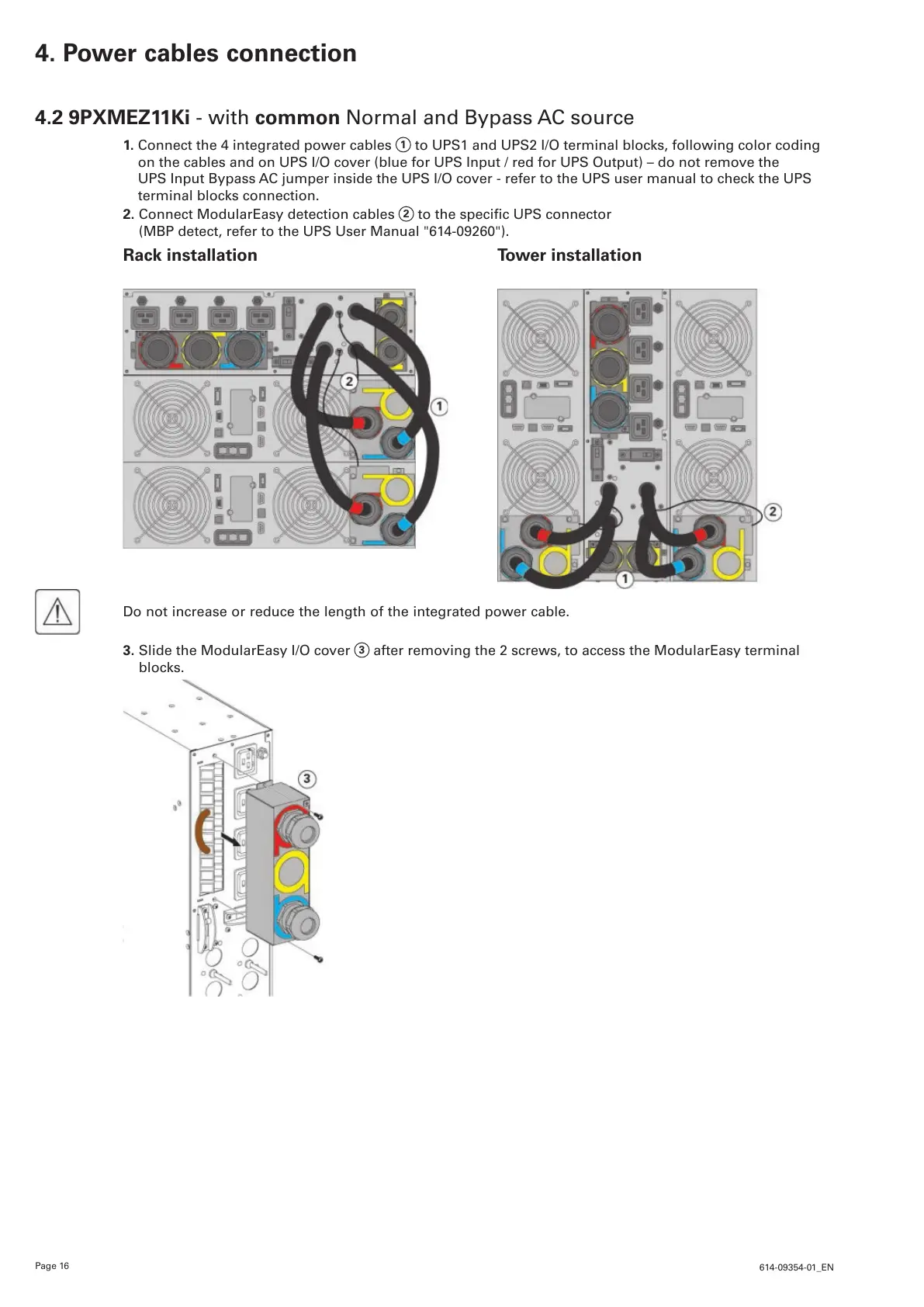
4.2 9PXMEZ11Ki - with common Normal and Bypass AC source
1. Connect the 4 integrated power cables
1
to UPS1 and UPS2 I/O terminal blocks, following color coding
on the cables and on UPS I/O cover (blue for UPS Input / red for UPS Output) – do not remove the
UPS Input Bypass AC jumper inside the UPS I/O cover - refer to the UPS user manual to check the UPS
terminal blocks connection.
2. Connect ModularEasy detection cables
2
tothespecicUPSconnector
(MBP detect, refer to the UPS User Manual "614-09260").
Rack installation Tower installation
Do not increase or reduce the length of the integrated power cable.
3. Slide the ModularEasy I/O cover
3
after removing the 2 screws, to access the ModularEasy terminal
blocks.
4. Power cables connection
 Loading...