Page 23
614-09354-01_EN
ENGLISH
5.3 UPS replacement with ModularEasy
5.3.3 9PXMEZ11Ki
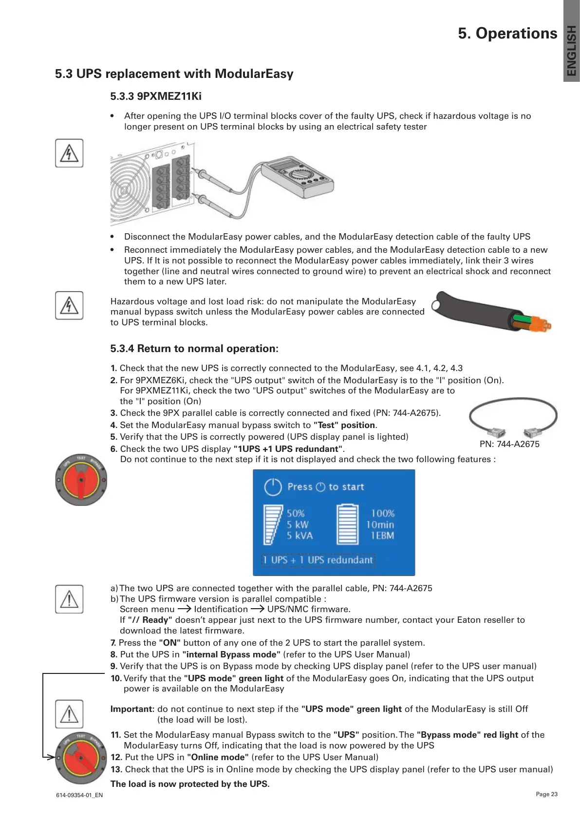
• After opening the UPS I/O terminal blocks cover of the faulty UPS, check if hazardous voltage is no
longer present on UPS terminal blocks by using an electrical safety tester
• Disconnect the ModularEasy power cables, and the ModularEasy detection cable of the faulty UPS
• Reconnect immediately the ModularEasy power cables, and the ModularEasy detection cable to a new
UPS. If It is not possible to reconnect the ModularEasy power cables immediately, link their 3 wires
together (line and neutral wires connected to ground wire) to prevent an electrical shock and reconnect
them to a new UPS later.
Hazardous voltage and lost load risk: do not manipulate the ModularEasy
manual bypass switch unless the ModularEasy power cables are connected
to UPS terminal blocks.
5.3.4 Return to normal operation:
1. Check that the new UPS is correctly connected to the ModularEasy, see 4.1, 4.2, 4.3
2. For 9PXMEZ6Ki, check the "UPS output" switch of the ModularEasy is to the "I" position (On).
For 9PXMEZ11Ki, check the two "UPS output" switches of the ModularEasy are to
the "I" position (On)
3.Checkthe9PXparallelcableiscorrectlyconnectedandxed(PN:744-A2675).
4. Set the ModularEasy manual bypass switch to "Test" position.
5. Verify that the UPS is correctly powered (UPS display panel is lighted)
6. Check the two UPS display "1UPS +1 UPS redundant".
Do not continue to the next step if it is not displayed and check the two following features :
a) The two UPS are connected together with the parallel cable, PN: 744-A2675
b) The UPS firmware version is parallel compatible :
Screen menu Identification UPS/NMC firmware.
If "// Ready"doesn’tappearjustnexttotheUPSrmwarenumber,contactyourEatonresellerto
downloadthelatestrmware.
7. Press the "ON" button of any one of the 2 UPS to start the parallel system.
8. Put the UPS in "internal Bypass mode" (refer to the UPS User Manual)
9. Verify that the UPS is on Bypass mode by checking UPS display panel (refer to the UPS user manual)
10. Verify that the "UPS mode" green light of the ModularEasy goes On, indicating that the UPS output
power is available on the ModularEasy
Important: do not continue to next step if the "UPS mode" green light of the ModularEasy is still Off
(the load will be lost).
11. Set the ModularEasy manual Bypass switch to the "UPS" position. The "Bypass mode" red light of the
ModularEasy turns Off, indicating that the load is now powered by the UPS
12. Put the UPS in "Online mode" (refer to the UPS User Manual)
13. Check that the UPS is in Online mode by checking the UPS display panel (refer to the UPS user manual)
The load is now protected by the UPS.
5. Operations
PN: 744-A2675
 Loading...