User manual SEFELEC 5x Series 35 v1.06
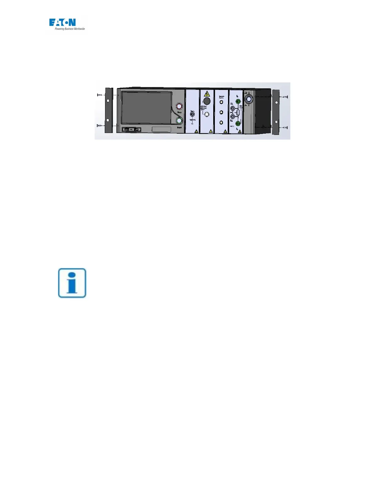
Position the brackets on each side of the device as in the drawing and secure with the 4 screws.
See below:
4 - Fitting the bay kit: Fit the 2 runners, adjust them in height according to the equipment to be
installed in the bay.
5 - Install the device on the runners and slide it so that the 2 brackets on the rails of the bay on
the front panel are abutting. Then fix the device to the bay with the screws in the kit.
In the case of a device with the outputs in the rear face. Provide a deeper bay of 800 mm mini-
mum.
NOTE
The air inlets of the device must be clear. The dimensions of the bay as
well as the mounting of the device must allow the movement of ai
r
around it in order to ensure a maximum operating temperature of 45°C.
 Loading...