Table of Contents
LIST OF FIGURES
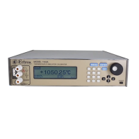
Figure 4-1: Front View of the Model 1140A 4-1
Figure 4-2: Main Menu 4-8
Figure 4-3: Thermocouple Menu 4-8
Figure 4-4: Instrument Mode Menu 4-10
Figure 4-5: Output Menu 4-11
Figure 4-6: Memory Menu with No Saved Files 4-12
Figure 4-7: Memory Menu with Saved Files 4-12
Figure 4-8: Sequence Menu 4-14
Figure 4-9: Data Logging Menu 4-16
Figure 4-10: Display Menu 4-17
Figure 4-11: Remote Menu 4-18
Figure 4-12: Web Browser Using the Ethernet Interface 4-20
Figure 4-13: Maintenance Menu 4-21
Figure 4-14: Diagnostics Menu 4-22
Figure 6-1: Remote Menu 6-1
Figure 7-1: Model 1140A Block Diagram 7-1
Figure 7-2: Source-mode Operation Diagram 7-5
Figure 7-3: Meter-mode Operation Diagram 7-5
Figure 8-1: Charging Supply Barrier Strip (High Voltage Guard Removed) 8-2
Figure 8-2: Fuse on Analog Assembly 8-4
Figure 9-1: Model 1140A Overall View 9-2
Figure 9-2: Model 1140A Overall View with Top Cover Removed 9-3
Figure 9-3: Battery Assembly and Charging Supply (Voltage Guard Removed) 9-4
Figure 9-4: Underside of Left Rear Corner 9-5
Figure 9-5: Digital and Keypad Assemblies 9-6
Figure 9-6: Left Side Panel 9-9
Figure 9-7: Analog Assembly 9-11
Figure 9-8: Binding Post Printed Circuit Board and TC Connector 9-11
Figure 9-9: Front Left Rail with Side Panel Removed 9-12
Figure 9-10: Wire Connections on Binding Post Printed Circuit Board 9-12
Figure 9-11: Power Supply Assembly 9-14
Figure 9-12: Display Assembly Area 9-17
Figure 11-1: Initial Operating Screen for Voltage Tests 11-2
Figure 11-2: Setup for Source Tests 11-3
Figure 11-3: Setup for Meter Tests 11-4
Figure 11-4: Initial Operating Screen for Temperature Tests 11-5
Figure 11-5: Operating Screen for Thermocouple Alloy Tests 11-7
Figure 11-6: Setup for Alloy Test at Binding Posts 11-7
Figure 11-7: Setup for Alloy Test at Thermocouple Connector 11-8
Figure 11-8: Setup for Output-current Test 11-8
Figure B-1: Type E Thermocouple Calibration Setup B-2
v