Maintenance and Repair
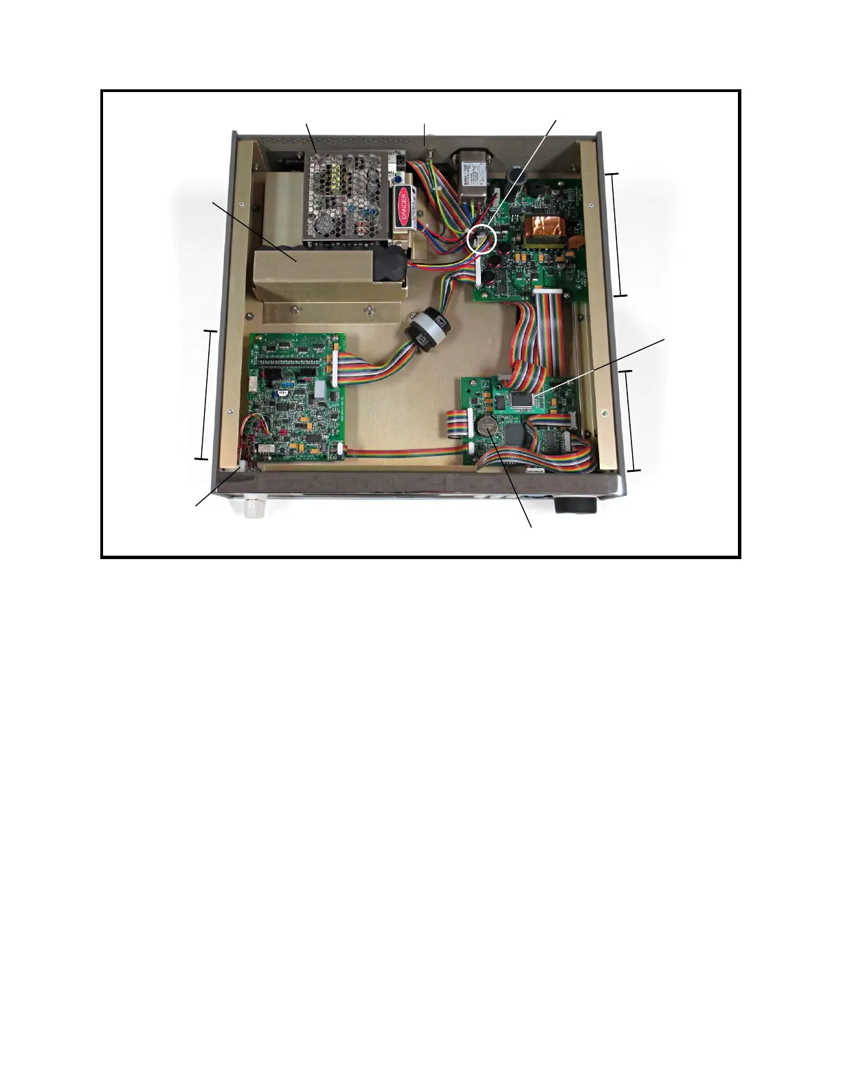
Figure 9-2: Model 1140A Overall View with Top Cover Removed
2 Top Cover Installation
1. Plug the four-pin battery connector into the power-supply assembly. See Figure 9-2.
2. Place the top cover on top of the Model 1140A with the flange toward the front.
3. Using a 3/16″ slot screwdriver, install the four captive screws on the top cover.
Tighten them to 5 in-lb torque.
4. If any components have been repaired or replaced, it is recommended to perform an
alignment (see Section X) followed by a calibration (Section XI) to verify the unit’s
functionality.
3 Battery Removal
Refer to Figure 9-2 for the locations of the components mentioned in this procedure.
1. Follow Procedure 1 for Top Cover Removal.
2. Using a 5/16″ socket, remove the two nuts and flat washers from the battery hold-
down bracket.
3. Remove the hold-down bracket and battery.
9-3
Battery BT1
GPIB
interface
(optional)
Digital
assembly
Charging supply
Battery
(optional)
Analog
assembly
TC connector
assembly
Battery connector
Front
Rear panel
Power-supply
assembly