Maintenance and Repair
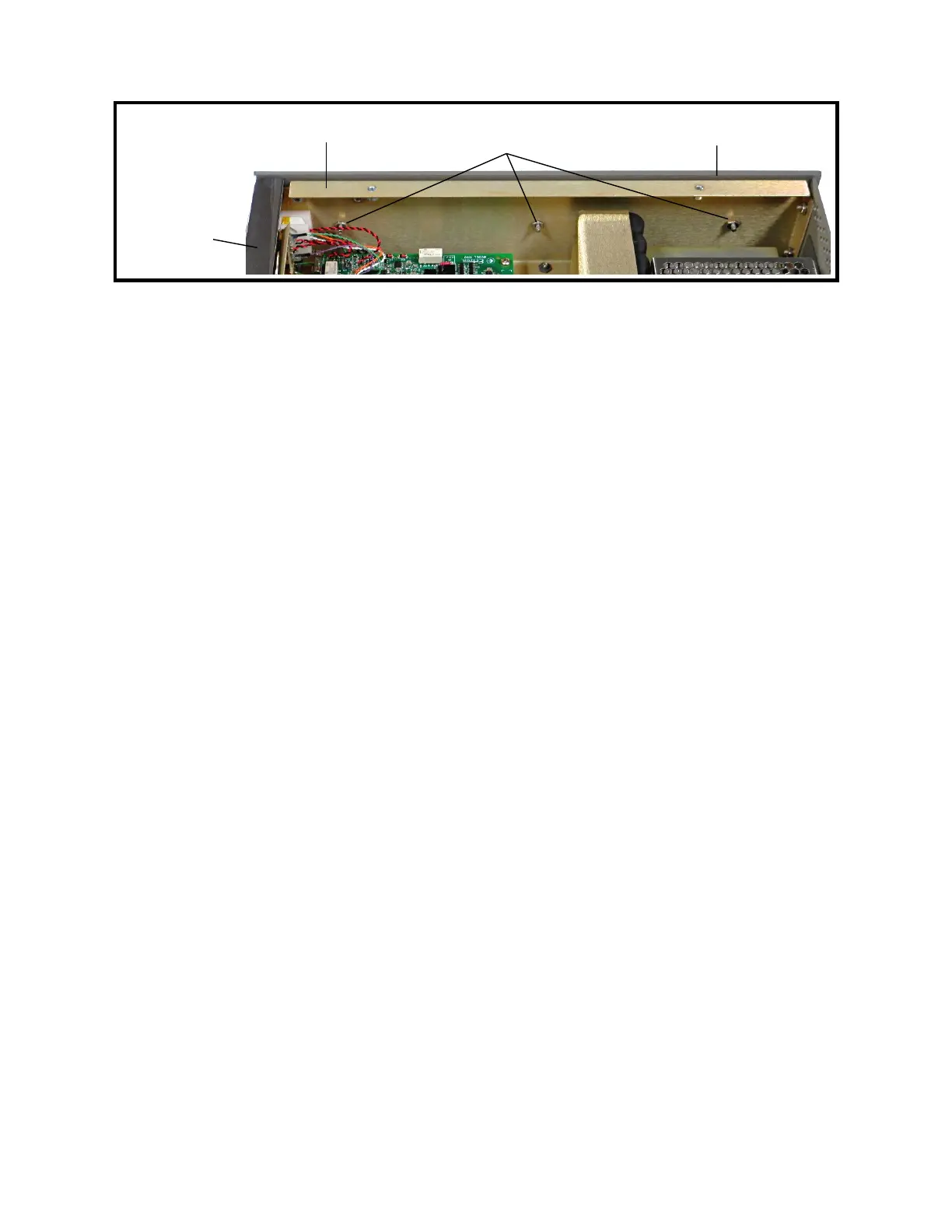
Figure 9-6: Left Side Panel
13 Left Side Panel and Front-panel Bar Removal
1. Follow Procedure 1 for Top Cover Removal.
2. Remove the three nuts and lock washers from the inside of the left side rail using a
5/16″ socket or wrench. See Figure 9-6.
3. Place the Model 1140A on its right side.
4. Gently pull the left side panel away from the Model 1140A. The front panel bars are
secured to the side panels by 1/16″ dowel pins. Be careful not to lose these pins.
5. Remove the top and bottom front-panel bars by gently pulling them out of the right
side panel. Remove the dowel pins from the right side and set them aside. As with the
left side, be careful not to lose the dowel pins in the right side of the bars.
14 Left Side Panel and Front-panel Bar Installation
1. Ensure that both top and bottom bars have all four dowel pins inserted as far as they
will go.
2. Place the Model 1140A on its right side.
3. Push the top bar into the right side panel, being careful to align the pins with the holes
in the right side panel.
4. Repeat the previous step with the bottom bar.
5. Push the left side panel into the left side of the instrument, being careful to align the
dowel pins in the top and bottom bars with the four holes in the left side panel.
6. Install the three nuts and lock washers to fasten the side panel to the left rail using a
5/16″ socket or wrench. Tighten to 10 in-lb torque. See Figure 9-6.
7. Follow Procedure 2 for Top Cover Installation.
15 Keypad Removal
1. Follow Procedure 1 for Top Cover Removal.
2. Follow Procedure 13 for Left Side Panel and Front-panel Bar Removal.
3. Remove the display connector from the rear of the LCD display assembly. See
Figure 9-5.
9-9
Left side rail
← Front
Left side panel
Top front-
panel bar
Three nuts holding
left side panel to left rail