Maintenance and Repair
Table 9-1: Charging Supply Barrier Strip Wires
Function Wire Color
+V
Red
−V or COM
Black
Ground Green/Yellow
L Brown
N Blue
7 Remote Interface Assembly Removal
1. Follow Procedure 1 for Top Cover Removal.
2. Unplug the appropriate remote interface ribbon cable from the digital assembly. See
Figure 9-5.
3. If removing a GPIB interface: Use a #2 Phillips screwdriver to remove the screw that
holds the GPIB interface board to the digital assembly. Remove the GPIB interface
board. See Figure 9-5.
4. Pull the remote interface ribbon cable out from under the power-supply assembly,
toward the rear of the unit.
5. Stand the instrument on its right side.
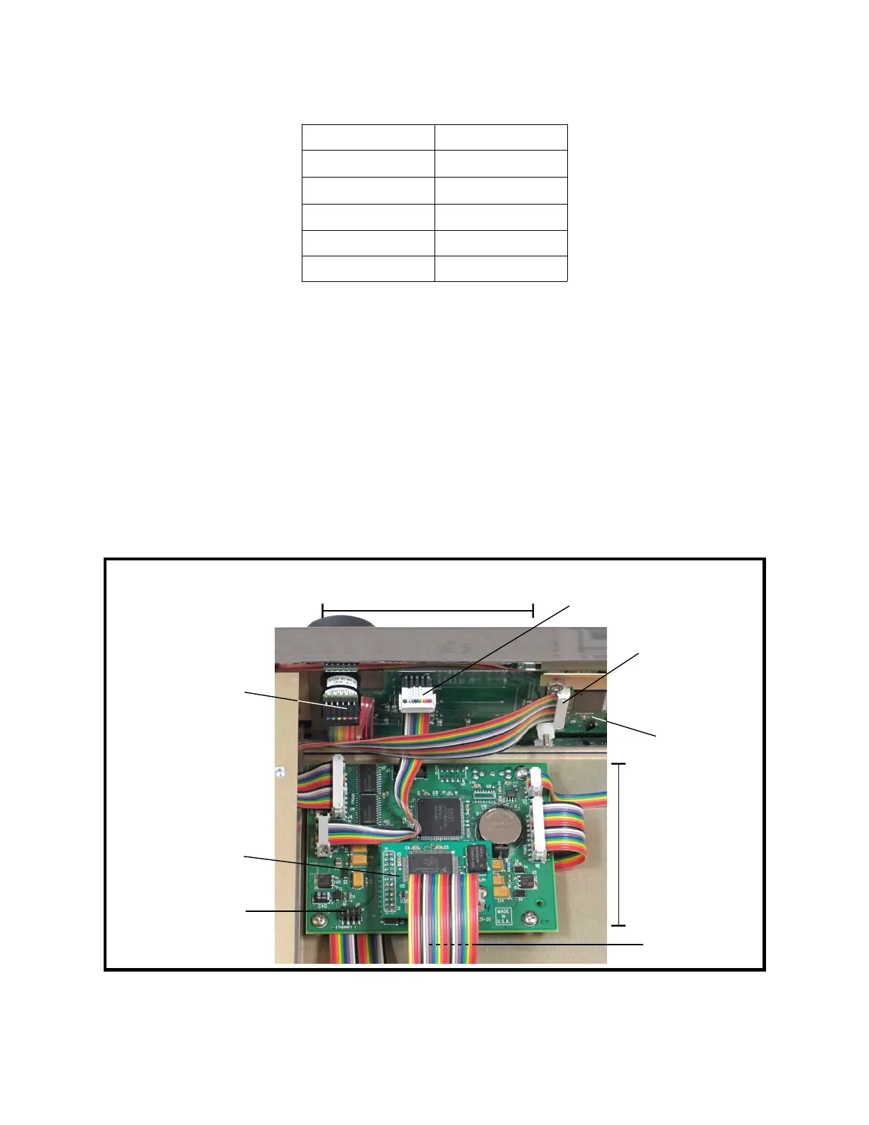
Figure 9-5: Digital and Keypad Assemblies
9-6
USB connector
(not shown)
Keypad
connector
Ethernet interface
header
Encoder
connector
Display
connector
↑ Front
LCD display
assembly
Keypad
assembly
Digital
assembly
GPIB interface
card (optional)