Maintenance and Repair
Orientation
Throughout this section, any references to the “left” or “right” side of the Model 1140A are given
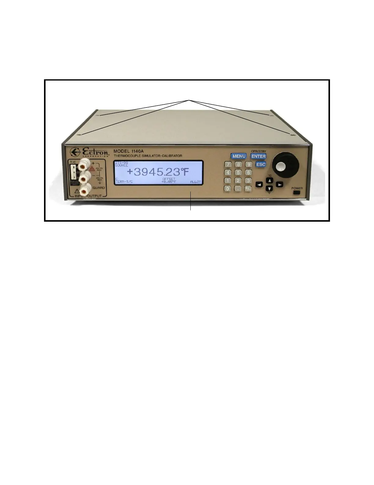
from the point of view of looking at the front of the unit. Refer to Figure 9-1 for an overview.
Figure 9-1: Model 1140A Overall View
Ribbon Cable Connections
RTV adhesive may be present on some or all ribbon cable connectors in the Model 1140A to
prevent disconnection during shipment. In the repair procedures below, when disconnecting a
ribbon cable note whether this adhesive is present. If necessary, cut it with a small, sharp blade to
free the connector.
When reconnecting any ribbon cable, RTV adhesive may be applied to prevent accidental
loosening of the connection in future handling or shipment.
1 Top Cover Removal
The following steps should be taken prior to performing any repair procedure:
1. Turn off the Model 1140A using the POWER button on the front panel.
2. Remove all connections to the Model 1140A including the ac power cord.
3. Use a 3/16″ slot screwdriver to loosen the four captive screws on the top cover. See
Figure 9-1.
4. Remove the top cover.
5. If a battery is installed: Locate the four-pin battery connector, shown in Figure 9-2,
and unplug it from the power-supply assembly.
9-2
Front panel
Right side
Left side
Top panel
Four screws for
top cover