Maintenance and Repair
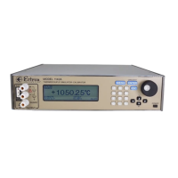
Figure 9-7: Analog Assembly
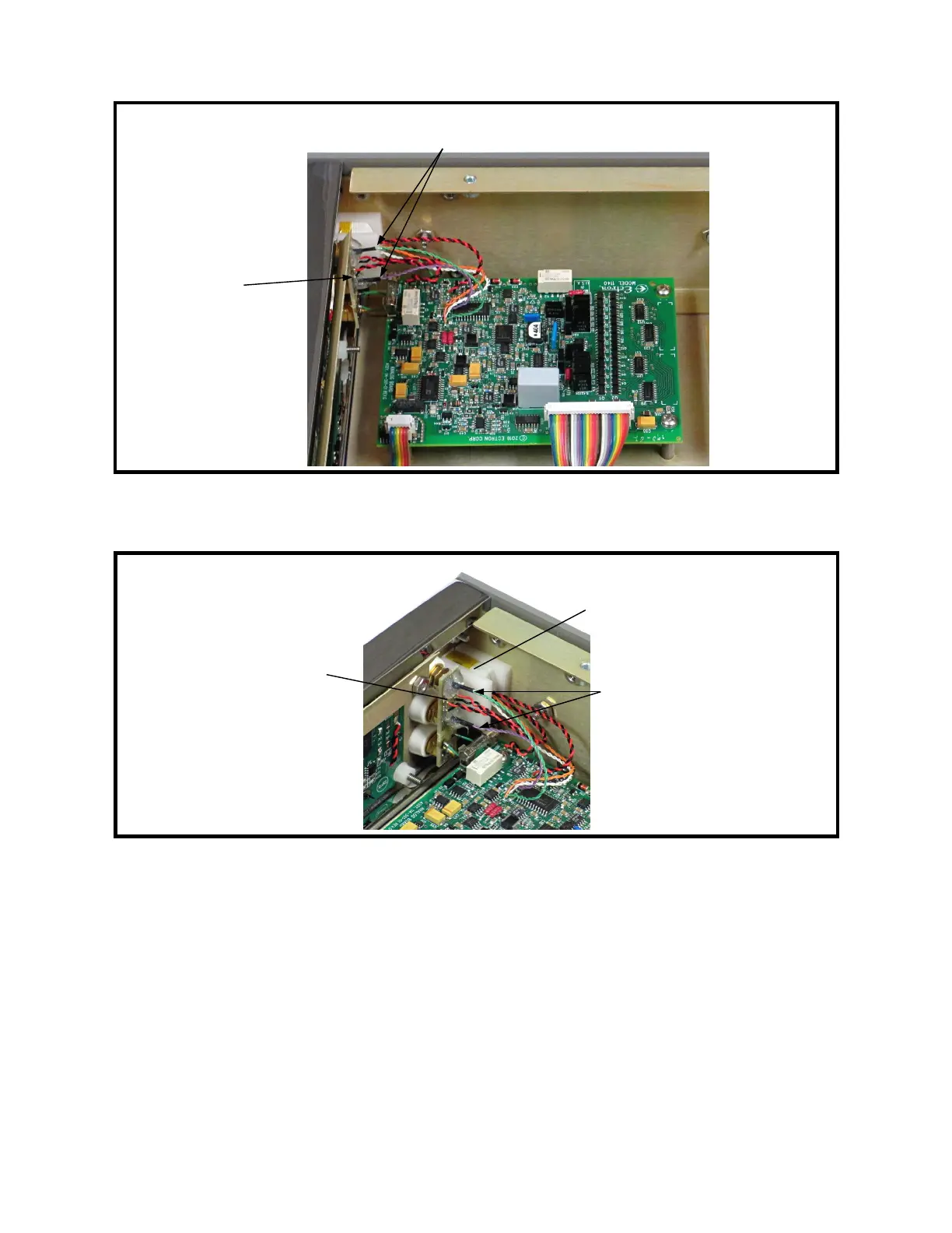
Figure 9-8: Binding Post Printed Circuit Board and TC Connector
6. Unsolder the two pairs of black and red twisted wires from the binding post printed
circuit board. See Figure 9-8.
7. Unsolder the two green guard wires from the binding post printed circuit board.
8. Remove the two thermocouple (TC) connector mounting screws from the left rail
using a #1 Phillips screwdriver. See Figure 9-9.
9. Carefully remove the analog assembly and TC connector assembly from the
instrument. Support the TC connector assembly to prevent stressing the wires that
connect it to the analog assembly.
9-11
Front
Binding post
PC board
TC connector between
two mounting blocks
Binding post
temperature sensor wires
← Front
Binding post
PC board
Binding post temperature
sensor wires