Maintenance and Repair
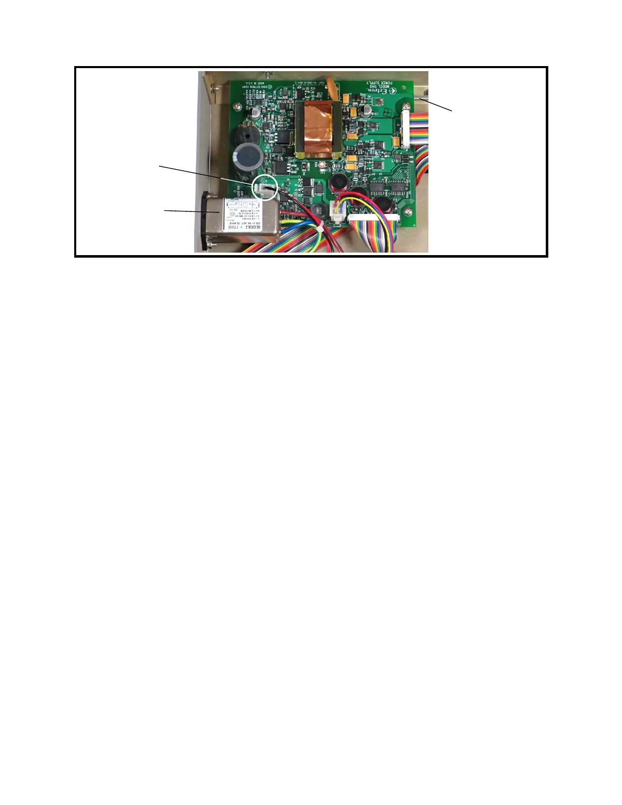
Figure 9-11: Power Supply Assembly
20 Power-supply Assembly Installation
1. Hold the power-supply assembly over the Model 1140A and insert the power switch
extension shaft through the cutout in the front panel.
2. Lower the power-supply assembly into the chassis in front of the ac line filter.
3. While holding the power switch extension shaft, install the push-button cap of the
POWER button onto the end at the front panel.
4. Slide the power-supply assembly back under the ac line filter until the four mounting
holes line up with the standoffs. While sliding it back, guide the push-button cap of
the power switch into the front-panel cutout.
5. Install the four power-supply assembly mounting screws and lock washers, located
near the four corners of the board, using a #2 Phillips screwdriver. Tighten to 6 in-lb
torque.
6. Plug the two interconnect ribbon cables into the power-supply assembly. Ensure
proper polarity, with Pin 1 (the edge of the cable with a brown wire) of each cable
toward the rear or right side of the unit. See Figure 9-11.
7. Plug in the two-pin charging supply connector. See Figure 9-11.
8. Follow Procedure 2 for Top Cover Installation.
21 Front-panel Assembly Removal
1. Follow Procedure 1 for Top Cover Removal.
2. Follow Procedure 13 for Left Side Panel and Front-panel Bar Removal.
3. Remove the keypad connector from the rear of the keypad assembly. See Figure 9-5.
4. Remove the display connector from the rear of the LCD display assembly. See
Figure 9-5.
5. Remove the encoder connector from the rear of the keypad assembly. See Figure 9-5.
9-14
Power switch
extension shaft
Ac line filter
→ Front
Charging
supply
connector