SECTION X
10 ALIGNMENT
GENERAL
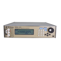
The Model 1140A is a self-aligning instrument. Once VOLTAGE ALIGNMENT and TERMINAL
ALIGNMENT have been performed, the instrument is ready for use. There are no potentiometers to
set or resistors or capacitors to select. Allow a 30 minute warm-up before performing the
alignment procedure.
EQUIPMENT REQUIRED
• Ten-volt dc standard: Fluke Model 732B or equivalent. The uncertainty of the voltage
must be <75 µV (for a minimum test-accuracy ratio, TAR, of 4:1) and be within the range
of 9.9 V dc to 10.1 V dc.
• Shorting bar or cable: Pomona Electronics Model 5145 or equivalent.
• Null detector/microvoltmeter: Keithley Model 155 or equivalent. This unit must be
capable of resolving 1 µV dc.
• Low-thermal cable, Pomona 1756-24 or equivalent.
• Ice-point bath: Hart Model 9101 zero-point dry well or equivalent. A properly made and
maintained distilled-water ice bath can also be used. An uncertainty of 0.01°C is required.
• Calibrated Type T thermocouple (24 AWG recommended) with its error at 26°C
3
, if any,
known to the nearest tenth of a microvolt. Appendix B provides a procedure to calibrate a
thermocouple. If copper wires are attached to the thermocouple, the copper ends should
be shorted together. The insulation on the thermocouple wire ends should be stripped
back approximately 0.4″ (10 mm).
• Optional: Cover to shield terminals from air flow, such as Ectron P/N 114-523-01.
• For units with firmware version 4.40 and above, the following items from the Calibration
Procedure are also needed during alignment:
• Digital multimeter (DMM), Hewlett Packard Model 3458A (with Option 02) or
equivalent.
• Four-wire Type E thermocouple (24 AWG recommended), calibrated at 26°C
3
with
known microvolt error and with bare-wire ends for alloy and copper wires. Appendix
B provides a procedure to calibrate a thermocouple. The insulation on the
thermocouple wire ends should be stripped back approximately 0.4″ (10 mm).
PRELIMINARY
Turn the power to the Model 1140A off, set the alignment switch (recessed in a square hole in the
bottom cover just to the rear of the KEYPAD) to the right to enable ALIGNMENT, and turn the
Model 1140A on.
3 See Footnote 5 in Appendix B.
10-1