xii
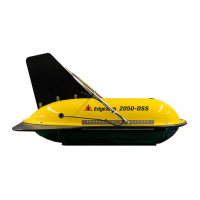
2050-DSS Side Scan and Sub-Bottom System 0024048_REV_A
2.0 SPECIFICATIONS ....................................................................................................................... 2-6
2.1 2050-DSS Tow Vehicle Specifications ........................................................................................ 2-6
2.1.1 2050-DSS Towfish Physical Specifications ............................................................................ 2-6
2.1.2 2050-DSS Sonar Specifications ............................................................................................. 2-7
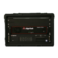
2.2 Starmux IV Topside Specifications ............................................................................................. 2-8
2.3 Tow Cable Specifications ........................................................................................................... 2-9
2.3.1 Armored Tow Cable Specifications ....................................................................................... 2-9
2.4 2050-DSS Mechanical Drawings .............................................................................................. 2-11
2.4.1 2050-DSS Towfish Mechanical Drawing ............................................................................. 2-11
2.4.2 2050-DSS Electronic Bottle and End Cap Configuration Drawing ....................................... 2-12
2.4.3 2050-DSS Sub Bottom Transducer Drawing ....................................................................... 2-13
2.4.4 2050-DSS PVDF Hydrophone Drawing ................................................................................ 2-14
2.4.5 2050-DSS Side Scan Transducer Drawing ........................................................................... 2-15
2.4.6 2050-DSS Test Cable Drawing ............................................................................................. 2-16
2.4.7 2050-DSS Starmux IV Topside Digital Link Drawings .......................................................... 2-17
3.0 TECHNICAL DESCRIPTION ....................................................................................................... 3-19
3.1 2050-DSS Tow Vehicle Technical Description .......................................................................... 3-19
3.1.1 2050-DSS Towfish System Diagram .................................................................................... 3-20
3.1.2 2050-DSS Sonar Processor Diagram ................................................................................... 3-21
3.1.3 2050-DSS Sonar Processor Endcap Diagram ....................................................................... 3-22
3.1.4 2050-DSS Main I/O Interface (J1) ....................................................................................... 3-23
3.1.5 2050-DSS Magnetometer I/O Interface (J2) ....................................................................... 3-24
3
.1.6 2050-DSS Responder I/O Interface (J8) .............................................................................. 3-25
3.2 2050-DSS Starmux IV Topside Technical Description .............................................................. 3-26
3.2.1 Starmux IV Controls, Indicators, and Connections ............................................................. 3-26
3.2.2 Starmux IV 2050 Rack Mount Controls, Indicators, and Connections ................................ 3-28
4.0 SETUP AND ACTIVATION ........................................................................................................ 4-31
4.1 Unpacking and Inspection ....................................................................................................... 4-31
4.2 Power Requirements ............................................................................................................... 4-31
4.2.1 Use of an Uninterrupted Power Supply .............................................................................. 4-31
4.2.2 Change to a Non-US Power Plug ......................................................................................... 4-32
4.3 Topside Processor Placement .................................................................................................. 4-32