4-44
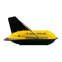
2050-DSS SIDE SCAN AND SUB-BOTTOM SYSTEM 0024048_REV_A
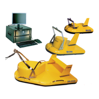
Figure 4-14: Tow Bridle Arm Removal Hardware
4.7.2 Tow Bridle Adjustment
The bridle is shipped in a default position that should accommodate typical towing parameters. If they are
changed for any reason, the bridle’s position can be altered to correct the vehicle’s pitch and provide
proper sensor orientation and stability. Moving the bridle position forward will result in a nose-up positive
pitch position. Moving the bridle aft will result in a nose-nose down negative pitch correction.
Instructions:
The bridle is adjusted by removing the bridle and reinstalling it to a more suitable hole position on the
tow bridle mounting rails. Instructions for bridle removal are found in the T
OW BRIDLE REMOVAL
INSTRUCTIONS above and reinstalled using the TOW BRIDLE INSTALLATION INSTRUCTIONS below.
4.7.3 Tow Bridle Installation
The tow bridle is attached to the 2050-DSS Vehicle with two Bolt, washer, nut, and split ring hardware
sets on the port and starboard side of the vehicle. The tow vehicle's power and data cable also runs up
the starboard side of the vehicle and bridle arm and is lashed to the arm and rail with cable ties. To install
the tow bridle lift and position the bridle at the default hole position, fasten using hardware, run the
power and data cable up the starboard bridle arm and lash the cable to the tow bridle arm and mounting
rail using cable ties.
Washers
Washer