5-59
=
6. Push the power and data cable through the hole it emerges from in the upper-shell.
7. Carefully lift the upper-shell from the vehicle and set it aside. If the rudder is attached, do not lay
the shell down on it as it is not designed to bear the upper shell's weight.
8. The inner-tow vehicle should now be exposed and ready for service.
Upper-Shell Assembly Instructions:
1. Carefully lift the upper-shell and place it on the lower shell lining it up the wing and 13-bolt holes
while threading the power and data cable through the starboard hole in the upper-shell.
2. Set the [2] bridle mounting rails on the tow vehicle over the eight mounting holes they were
removed from. The mounting rail risers should be oriented toward the outside of the vehicle.
3. Insert the [8] 3/8” bolts through the [8] 3/8” split-lock washers, the [8] 3/8” standard flat washers,
the [2] bridle mounting rails, and the upper and lower shells. Align the [2] threaded tow plates
under the lower shell flange and thread the [8] 3/8” bolts into the tow plate using the 9/16”
wrenches.
4. Insert the [5] 3/8” bolts through the [5] 3/8” split-lock washers, the [5] 3/8” fender washers, and
the upper and lower shells. Thread the [5] 3/8” hex nuts and [5] 3/8” fender washers onto the [5]
3/8” bolts securing the top shell using the 9/16” wrenches.
5. Reinstall the tow vehicle bridle as described in the T
OW BRIDLE INSTALLATION section of this manual.
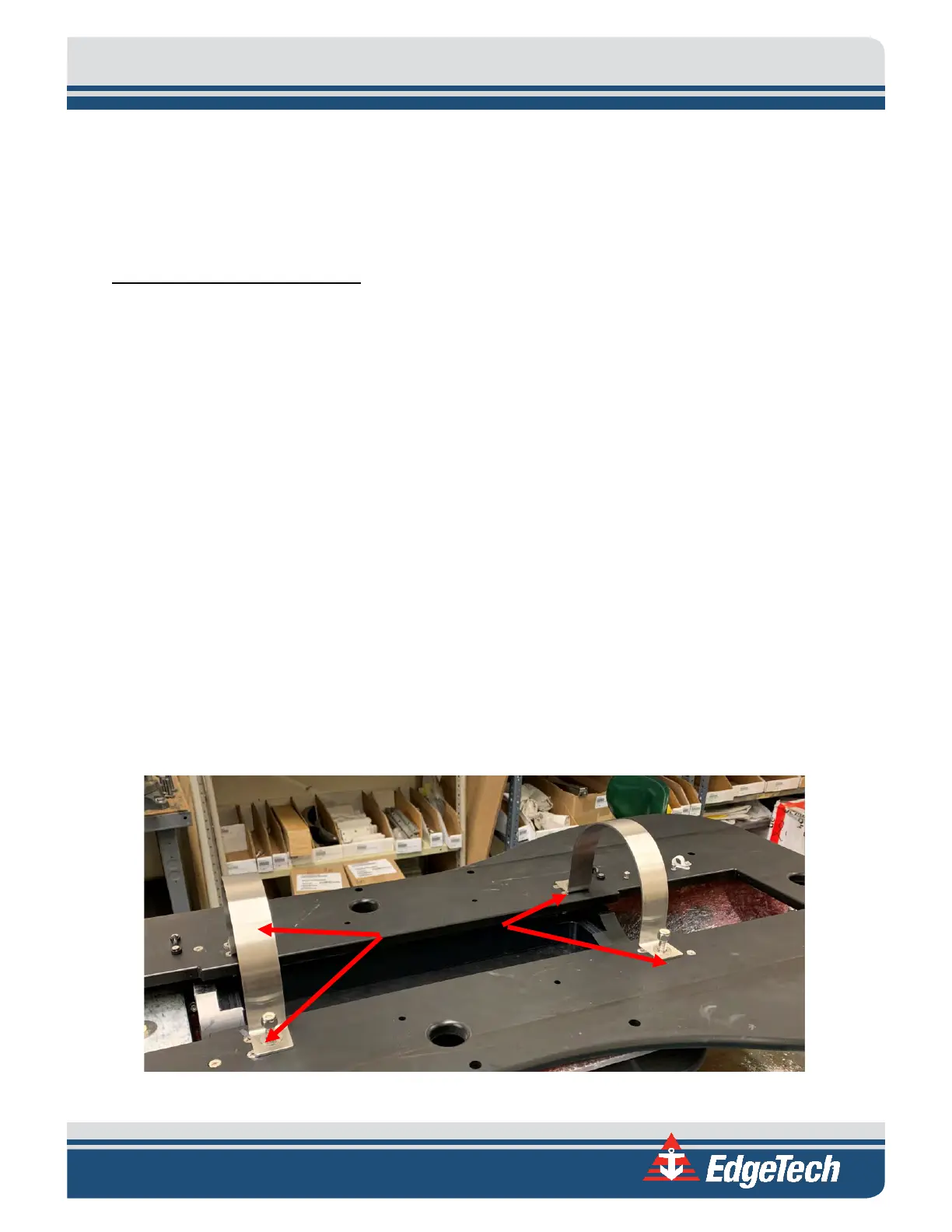
5.6 Sonar Processor Removal and Installation
The horizontally mounted sonar processor can be removed by opening the top cover of the tow vehicle,
disconnecting the cabling, removing the two bottle clamps by unthreading the four hex bolt assemblies
securing it, and lifting the processor bottle out of the tow vehicle.
Figure 5-7: 2050-DSS Sonar Processor Mounting Assembly
Assemblies