xvii
LIST OF TABLES
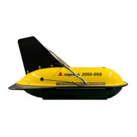
Table 2-1: 2050-DSS Towfish Specifications .............................................................................................. 2-6
Table 2-2: 2050-DSS Sonar Specifications .................................................................................................. 2-7
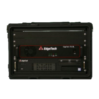
Table 2-3: Starmux IV Specifications .......................................................................................................... 2-8
Table 2-4: Armored Cable A309183 Specifications .................................................................................... 2-9
Table 2-5: Armored Cable A392799 Specifications .................................................................................... 2-9
Table 2-6: Armored Cable A320327 Specifications .................................................................................. 2-10
Table 3-1: Main I/O Interface Cable Pin Outs .......................................................................................... 3-23
Table 3-2: Magnetometer Interface Cable Pin Outs ................................................................................ 3-24
Table 3-3: Responder IO Pin Outs ............................................................................................................ 3-25
Table 3-4: Starmux IV Controls, Indicators, and Connections ................................................................. 3-26
Table 3-5: Starmux IV Rack Mount Controls, Indicators, and Connections ............................................. 3-28
Table 4-1: AC Power Wiring Wire Colors for Conversion ......................................................................... 4-32
Table 4-2: 2050-DSS Factory Installed Component IP Addresses ............................................................ 4-37
Table 4-3: 2050-DSS Tow Bridle Removal Tools ...................................................................................... 4-43
Table 4-4: 2050-DSS Tow Bridle Installation Tools and Hardware .......................................................... 4-45
Table 4-5: Cable A320327 Layback Chart ................................................................................................. 4-51
Table 4-6: Cable A302799 Layback Chart ................................................................................................. 4-52
Table 4-7: Cable A309183 Layback Chart ................................................................................................. 4-53
Table 5-1: Tail Rudder Removal and Installation Tools and Hardware .................................................... 5-55
Table 5-2: Upper-Shell Disassembly and Assembly Tools and Hardware ................................................ 5-58
Table 5-3: Sonar Processor Installation and Removal Tools and Hardware ............................................ 5-60
Table 5-4: Sub-Bottom Transducer Removal and Installation Tools and Hardware ................................ 5-61
Table 6-1: Starmux IV Troubleshooting Table .......................................................................................... 6-65
Table 6-2: 2050-DSS Accessory Kit ........................................................................................................... 6-66