Chapter 2: Installation
14 ModuLaser Modular Aspirating Smoke Detector Installation Manual
Module and PCB layout
Backplane
The backplane is used to distribute power and communications to all modules in
the cluster. It also provides connections for inputs, outputs, and to legacy
devices. All field wiring is connected to the backplane via the cable knockouts on
the top, bottom, or back of the housing.
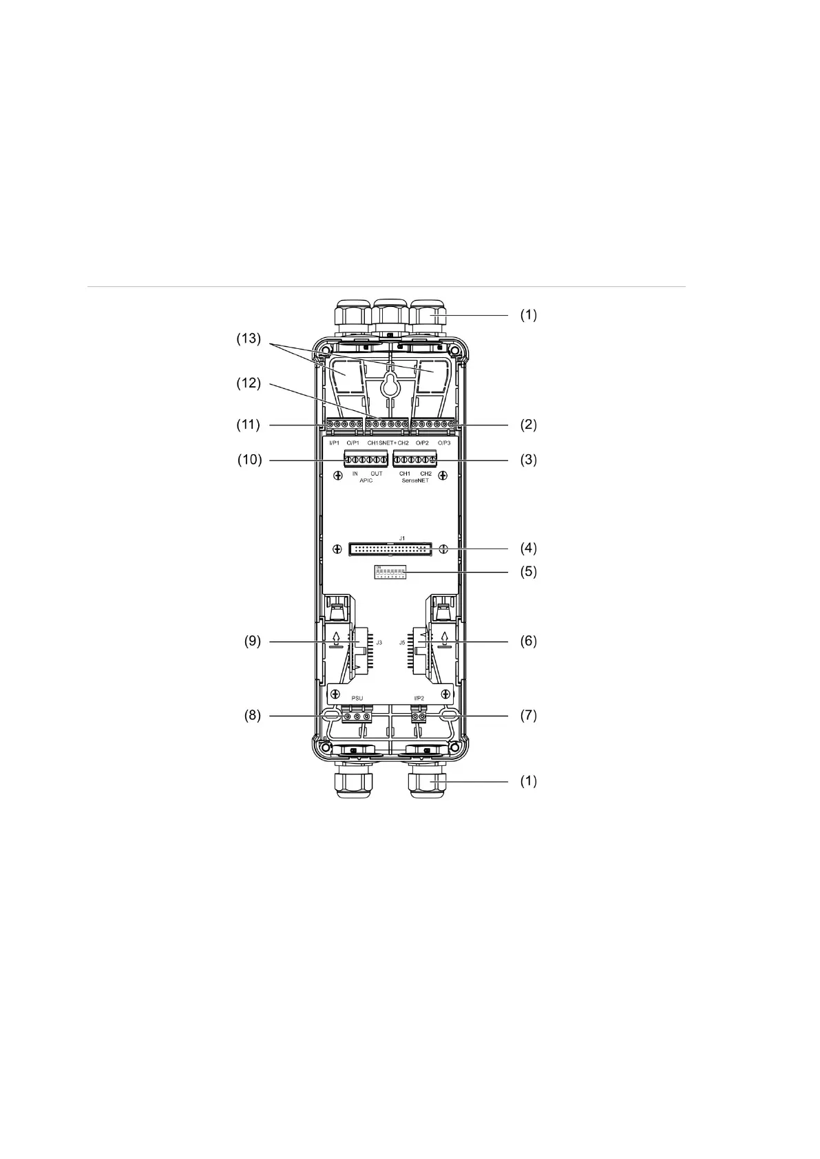
Figure 6: Backplane layout
. Cable glands (not supplied)
. O/P2 and O/P3 output connectors
. CH1 and CH2 SenseNET connectors for
bus or loop configuration
. J1 display and detector module connector
. Address DIP switch
. J5 SenseNET+ connector for adjacent
backplanes
8. Power supply connector
9. J3 SenseNET+ connector for adjacent
backplanes
10. APIC connector (used for connecting an
addressable loop)
11. I/P1 input and O/P1 output connectors
12. SenseNET+ connectors for bus or loop
configuration
13. Rear cable knockouts
Note: The SenseNET and APIC connectors are only used in display modules.