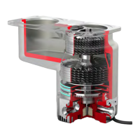
Figure 9 Typical pumping system with a nEXT pump
1. High-vacuum gauge 2. Vacuum system
3. Dierenal apertur
e 4. Foreline trap
5. Backing pump 6. Mist lter
7. Flexible bellows 8. Vacuum gauge
9. nEXT split-ow pump 10. Backing valve
11. WCX water cooler and connecons 12. Air cooler
13. Regulated purge gas supply 14. PRX purge restrictor
15. Vent valve 16. Alternave posion for vent valve
17. Inlet screen 18. Pump main inlet
19. Pump side inlet
1. High-vacuum gauge 2. Vacuum system
3. Dierenal aperture 4. Foreline trap
5. Backing pump 6. Mist lter
7. Flexible bellows 8. Vacuum gauge
9. nEXT split-ow pump 10. Backing valve
11. WCX water cooler and connecons 12. Air cooler
13. Regulated purge gas supply 14. PRX purge restrictor
15. Vent valve 16. Alternave posion for vent valve
17. Inlet screen 18. Pump main inlet
19. Pump side inlet
4.3.1 Inlet screen
WARNING: SHARP EDGES
Risk of injur
y. Trapped O-ring seals with integral inlet screens should be used (as
supplied). Replacement of these seals with alternaves without integral screens will
expose the risk of injury from sharp edges.
Page 34
B85200880_D - Ins
tallaon

 Loading...