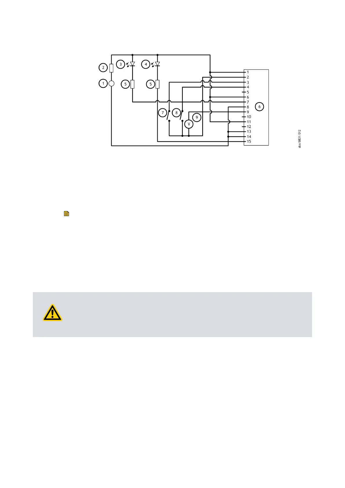
Figure 10 Logic interface c
onnecons - parallel control
1. 24 V d.c. electrical supply 2. Fuse
3. Oponal LED indic
ator ‑ system OK 4. Oponal LED indicator ‑ normal speed
5. Current limit resistor for LED 6. nEXT pump logic interface
7. Start switch 8. Oponal standby switch
9. Oponal voltmeter to monitor analogue
output
1. 24 V d.c. electrical supply 2. Fuse
3. Oponal LED indicator ‑ system OK 4. Oponal LED indicator ‑ normal speed
5. Current limit resistor for LED 6. nEXT pump logic interface
7. Start switch 8. Oponal standby switch
9. Oponal voltmeter to monitor analogue
output
Note:
The v
oltage supply to the pump controller can be more than 24 V. But the circuits
connected to the normal and fail line must have maximum external pull
‑
up voltage
rang as given in Table: Logic interface technical data on page 27.
4.6 Connect the parallel control and monitoring
To make the connecons for the parallel control and monitoring, use an applicable
mang half (not supplied).
CAUTION: BACK EMF SUPPRESSION DIODE
Risk of damag
e to equipment. If the normal and fail lines are used to drive the coils of
the d.c. relays, install a back EMF suppression diode in parallel with each relay coil to
protect the pump.
Connect the customer control equipment to the control input pins of the customer logic
interface mang half. Refer to Table: Logic interface connector pins on page 28 to
idenfy the connector pins of the logic interface.
The control inputs are:
▪ Start
▪ Standby speed
T
o acvate one of the control inputs, connect the control input pin to the 0 V control
reference. To start the pump, connect the pin 3 (Start / Stop) to the pin 2 (0 V reference).
To stop the pump, remove the connecon between the pin 3 and pin 2. To put the pump
in standby, connect the pin 4 (Standby) and pin 3 (Start / Stop) to pin 2 (0 V reference).
Page 40
B85200880_D - Ins
tallaon