number of pumps to a single master. Refer to Figure: R
S485 mul-drop connecon on
page 46.
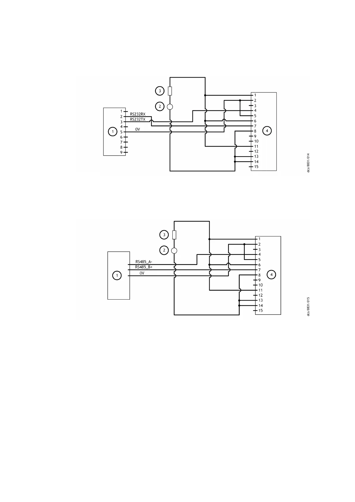
Figure 12 Logic interface connecons - RS232 serial control
1. RS232 interface on control equipment 2. 24 ‑ 48 V d.c. electric
al supply
3. Fuse 4. nEXT pump logic interface
1. RS232 interface on control equipment 2. 24 ‑ 48 V d.c. electrical supply
3. Fuse 4. nEXT pump logic interface
Figure 13 Logic interface connecons - RS485 serial control
1. RS485 interface on control equipment 2. 24 ‑ 48 V d.c. electric
al supply
3. Fuse 4. nEXT pump logic interface
1. RS485 interface on control equipment 2. 24 ‑ 48 V d.c. electrical supply
3. Fuse 4. nEXT pump logic interface
4.7.2 Serial enable
To send a serial message over the serial link, acvate the serial enable. To acvate the
serial enable, link the serial enable input signal (pin 5) to pin 2 of the customer logic
interface mang half.
We recommend you to incorporate this link into the serial communicaons cable so that
the serial enable is acvated only when the serial cable is connected. When the cable is
removed, serial enable will become inacve.
Serial enable operates as an interlock for the start commands sent over the serial
interface. If the pump operates in serial control mode (having been sent a serial start
command) and the serial enable becomes inacve, the pump will trigger a fail condion
Page 43
B85200880_D - Ins
tallaon