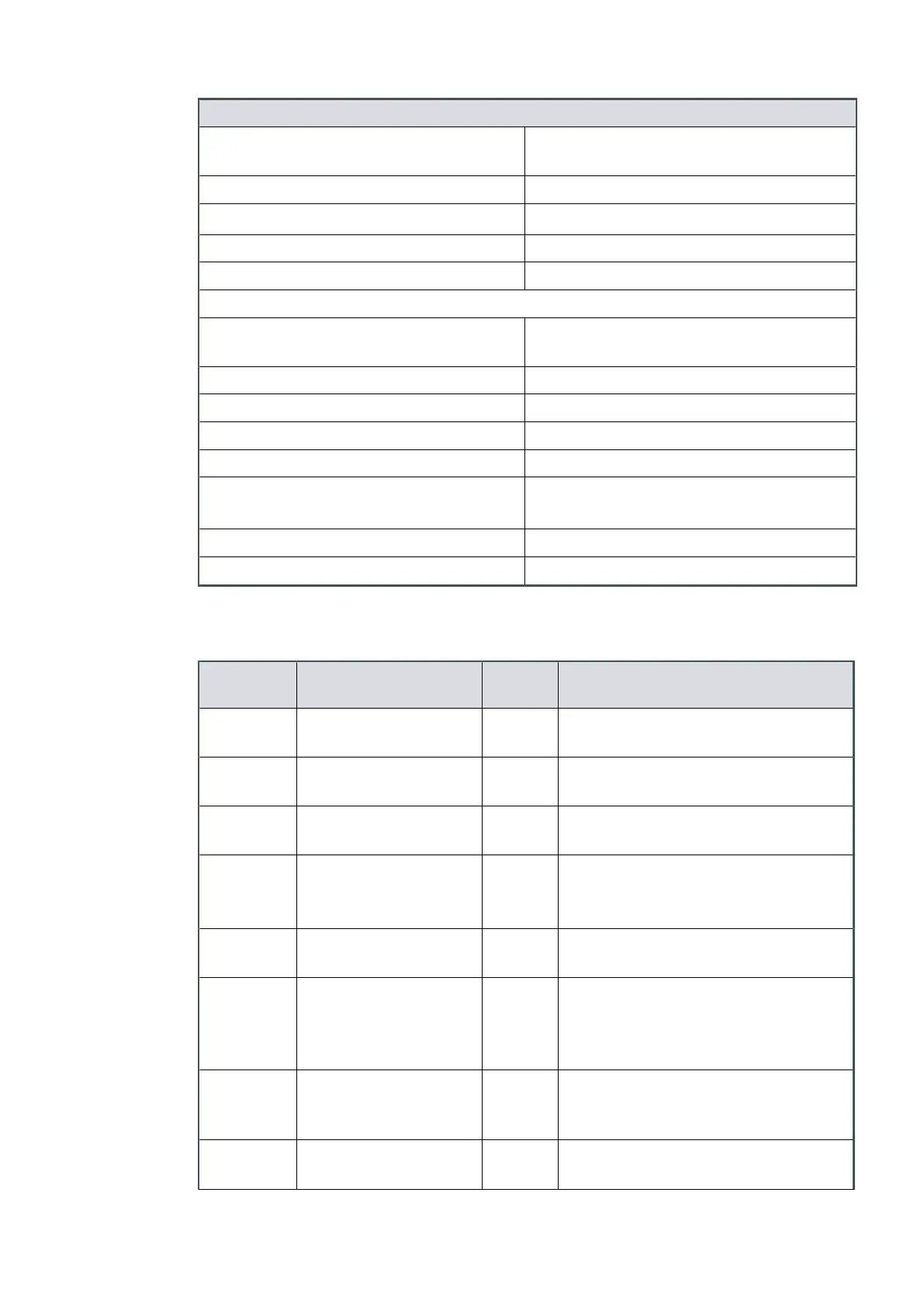
Logic interface descripon
Type Open collector transistor plus pull up
r
esistor.
< Normal speed (default 80%) OFF (4.7 k pull up + diode to 12 V d.c.)
³ Normal speed
ON (< 0.8 V d.c. sinking 10 mA)
Maximum current r
ang 10 mA
Maximum voltage rang 28.8 V d.c.
FAIL status output:
Type Open collector transistor plus pull up
resistor.
Fail OFF (4.7 k pull up + diode to 12 V d.c.)
OK ON (< 0.8 V d.c. sinking 10 mA)
Maximum current rang 10 mA
Maximum voltage rang 28.8 V d.c.
Analogue 10 V reference
+ 10 V d.c. analogue voltage reference
Unipolar output with diode protecon
Voltage accuracy ± 2% full scale
Output current
£ 5 mA f
or specied accuracy
* Mang half of connector not supplied.
Table 12
Logic interface connector pins
Pin
Number
Signal Polarity Use
1 Analogue Speed
Enable‑control Input
- Connect to Pin 2 (0 V) to enable
analogue speed control via Pin 9.
2 0 V Control Reference - 0 V reference for ALL control and status
signals listed within this table.
3 START / STOP - Control
Input
- Connect to Pin 2 (0 V) to START the
nXDS pump system.
4 STANDBY - Control
Input /
Serial-RX/RS485 A-
- Connect to Pin 2 (0 V) to enable
STANDBY speed when the SERIAL
ENABLE control input is inacve.
5 Serial Enable - Control
Input
- Connect to Pin 2 (0 V) to enable serial
communicaons.
6 RS232/RS485 - Control
Input
- Default conguraon is RS232 with Pin
6 unconnected.
Connect to Pin 2 (0 V) to enable RS485
serial communicaons.
7 FAIL ‑ Status Output/
Serial‑TX/RS485 B+
- Logic HIGH when a fail or fault
condion exists and the SERIAL ENABLE
control input is inacve.
8 0 V Control Reference - 0 V reference for all control and status
signals listed within this table.
Page 22
A73501880_G - Technical data
 Loading...


