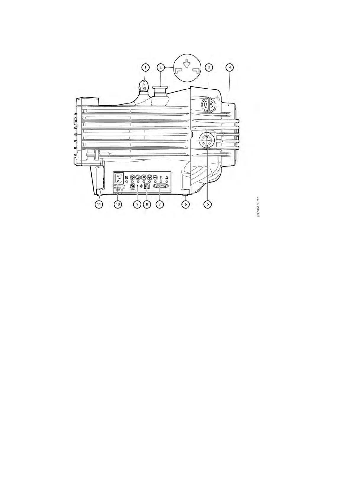
Figure 1 nXDS scroll pump
1. Liing e
ye 2. NW25 inlet port
3. Gas ballast control 4. Cooling fan
5. NW25 exhaust port 6. Rubber feet
7. 15‑way D‑type connector 8. USB port (service mode only)
9. User interface panel 10. Mains power connector
11. Secondary earth bond point
1. Liing eye 2. NW25 inlet port
3. Gas ballast control 4. Cooling fan
5. NW25 exhaust port 6. Rubber feet
7. 15‑way D‑type connector 8. USB port (service mode only)
9. User interface panel 10. Mains power connector
11. Secondary earth bond point
2.5 Logic interface
The pump controller can be operated via the 15‑way D‑type logic interface connector.
The signals on the logic interface are of the following types:
▪ Control inputs: these are switch‑type and analogue signals that controls the pump.
▪ Status outputs: these outputs idenfy the status of the system tab.
The logic interface is designed to support both serial control, parallel control and
monitoring, operang though one connector. For serial control either RS232 or RS485
can be selected.
For Control Modes refer to Table : nXDS Control modes on page 13.
For Logic interface data refer to Logic interface data on page 21.
2.6 Gas ballast control
To pump high vapour loads, gas ballast can be delivered into the pump to prevent
condensaon of the vapour carried by the pumped gases.
Air can be introduced to the low vacuum stages through the gas ballast control (Figure:
nXDS scroll pump on page 11, item 3). Alternavely, an inert gas such as nitrogen can be
Page 11
A73501880_G - Introducon
 Loading...


