Pin
Number
Signal Polarity Use
9 Analogue Speed ‑
Con
trol Input
- 0‑10 V analogue Input: 0 V = 0% Speed;
+ 10 V = 100% speed
10 Chassis/Screen - Screen
11 + 10 V Analogue
Reference ‑ Control
Output
Posive + 10 V analogue voltage reference
output: 5 mA, unipolar output, diode
protected.
12 Chassis/Screen - Screen
13 Not Connected - Unused control pin.
14 REMOTE ‑ Control Input - Connect to Pin 2 (0 V) to enable
remote control via Parallel or Serial
control modes.
15 NORMAL ‑ Status
output
- Logic LOW when the pump rotaonal
speed is at normal speed or above.
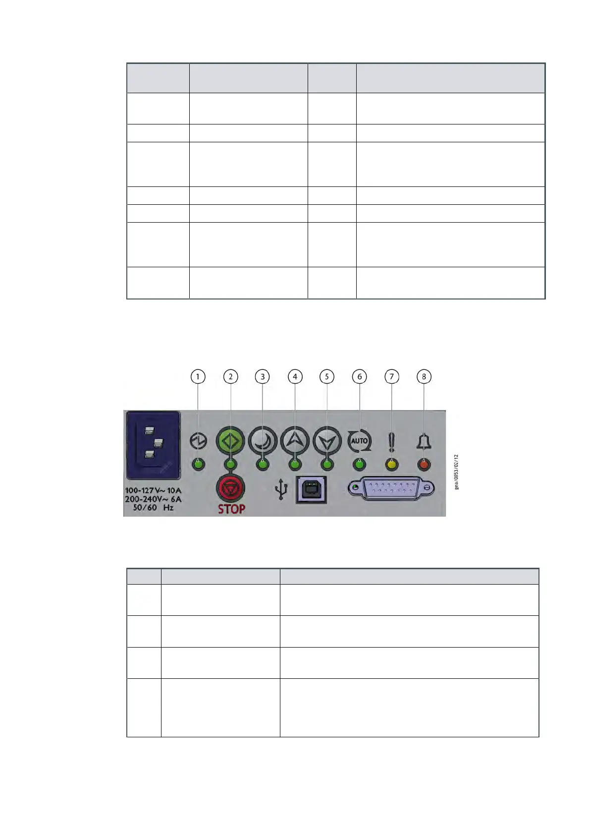
3.6 LED indicators
Figure 7 LED indicators
The nXDS pump has eight indicator LED's
Table 13
LED indicators
LED Descripon Details
1 Power indicator Indicates that electrical mains supply to the pump is
ON
2 Run indicator Indicates that the pump is running. Refer to Start and
stop on page 32.
3 Standby mode indicator Indicates that the Standby mode has been selected.
Refer to Standby on page 32.
4 Standby speed increase
indicator
The indicator will blink with every short push of the
Standby speed increase buon. The indicator will
remain ON when maximum standby speed has been
reached. Refer to Standby on page 32.
Page 23
A73501880_G - Technical data
 Loading...


