5.3 Parallel control and monitoring
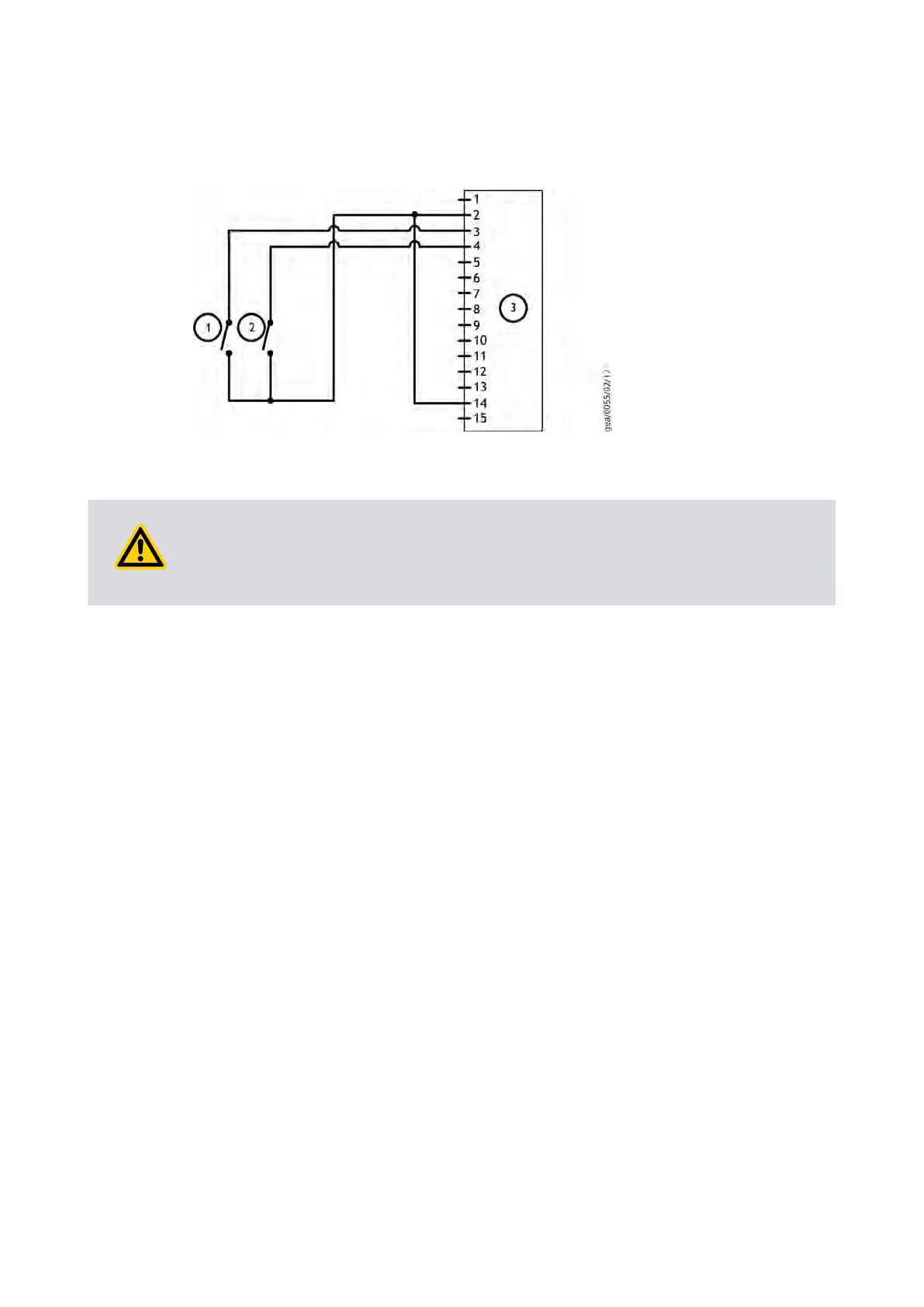
Figure 10 Logic interface c
onnecons - parallel control
1. Start switch 2. Standby switch (oponal)
3. nXDS pump logic interface
1. Start switch 2. Standby switch (oponal)
3. nXDS pump logic interface
CAUTION:
If using the normal and f
ail lines to drive the coils of d.c. relays, include a back EMF
suppression diode in parallel with each relay coil to protect the pump.
Connect the control equipment to the control input pins of the logic interface mang
half. Refer to Table: Logic interface technical data on page 21 to idenfy the logic
interface connector pins. The control inputs are as follows:
▪ Start
▪ Standby speed
▪ Analogue speed
T
o acvate any of these control inputs, connect the relevant control input (pin 14) to the
0 V control reference.
To monitor the normal status output, connect the control equipment to the Normal
status output (pin 15) and to pin 2 of the logic interface mang half. The output can be
used to control other devices in the pumping system. The output can drive a low power
relay of up to 24 V coil rang (up to 10 mA).
To monitor the fail status output, connect the control equipment to the fail output (pin
7) and to pin 2 of the logic interface mang half. The output can be used to control other
devices in the pumping system. The output can drive a low power relay of up to 24 V coil
rang (up to 10 mA).
5.4 Analogue speed control
The Analogue Speed input is a process control source which enables the nXDS Scroll
pump to run at variable operang speeds. This speed control source is an alternave to
standby speed control.
Page 33
A73501880_G - Oper
aon
 Loading...


