M561-00-880 Issue C
Page 4 © Edwards Limited 2012. All rights reserved.
Edwards and the Edwards logo are trademarks of Edwards Limited.
Introduction
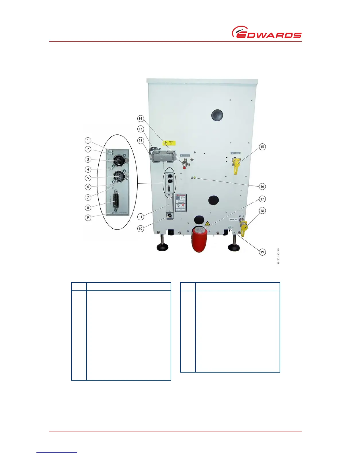
Figure 4 - The controls/connectors on the rear of the pump
Item Control/connector identification
1 Ethernet LAN LED (green)
2 Ethernet link LED (yellow)
3 Ethernet connection
4Power LED (green)
5System interface
6 Warning LED (yellow)
7 Running and Alarm LEDs (2 colours,
either green or red)
8 Accessory interface
9 MicroTIM in control LED (green)
10 EMS interface
11 Micro TIM connection (if fitted)
12 Electrical supply connection
13 Electrical connector locking
mechanism
14 Nitrogen purge connection
15 Cooling water supply connection
16 Protective earth (ground) stud
17 Exhaust gas outlet connection
18 Cooling water return connection
19 RF earth (ground) stud
Item Control/connector identification