© Edwards Limited 2012. All rights reserved. Page 57
Edwards and the Edwards logo are trademarks of Edwards Limited.
Appendix A1
M561-00-880 Issue C
Appendix A1 Pump display terminal
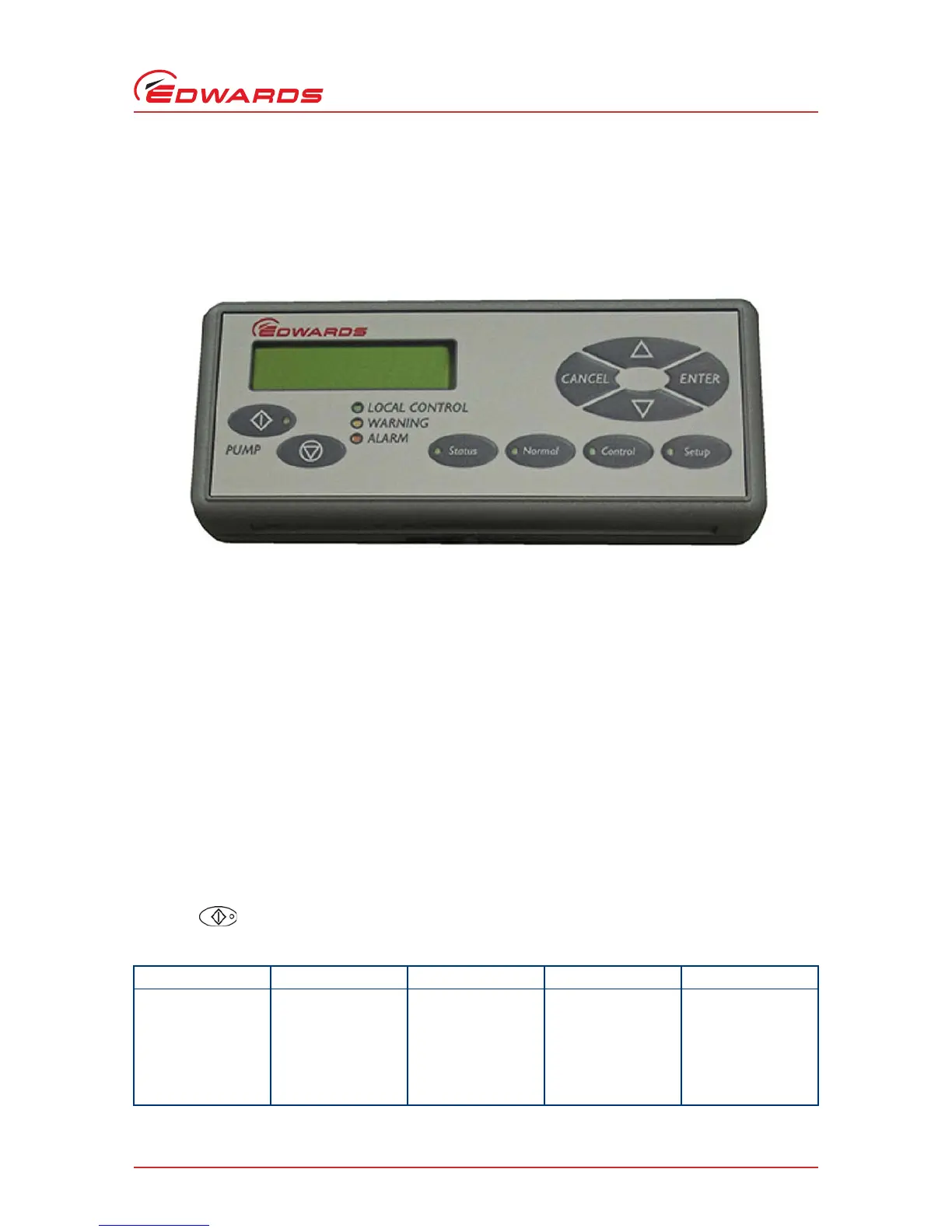
The PDT accessory provides pump on/off and status reporting. Warnings and alarms are also indicated to the user.
Up to two PDTs may be fitted to iXH and iXL systems, up to one PDT may be fitted to pXH systems.
Figure A1 - Pump display terminal
A1.1 LEDs
Local Control Green illuminates continuously when this PDT has control of the pump.
Pump ON Green (within the Pump Start button) illuminates to indicate that the pump is running.
Warning Yellow illuminates to indicate that a pump warning is present. It flashes when a new warning
occurs until it is acknowledged by pressing 'ENTER' when it goes continuous until the warning clears.
Alarm Red illuminates to indicate that a pump alarm is present. It flashes when a new alarm occurs
until it is acknowledged by pressing 'ENTER' when it goes continuous until the alarm clears.
A1.2 Pump start / stop and control
To Start or Stop the pump the PDT must be in control, indicated by the Local Control LED being illuminated.
To take or release control briefly press Control.
If something else is in control, error message 'Control locked' appears, refer to 'Control Holder' in the Status menu.
Press Start button PDT displays:
Table A1 - Pump start control
Pump State Local Control LED PDT display Operator Pump response
Stopped On START MENU Start
Pump
Press ENTER to con-
firm
Pump Starts
Running On Pump Running Press
CANCEL
Press CANCEL No change (running)
Stopped or Running Off No PDT Control Press
CANCEL
Press CANCEL No change
 Loading...