Do you have a question about the EES BSM and is the answer not in the manual?
Manual provides safe and efficient use of fault annunciating series BSM.
Manual is prerequisite for secure mounting and safe operation.
Manual is for qualified personnel with electrical site knowledge.
Security advice is indicated with symbols and signal words.
Annunciator intended for use according to manual and technical data.
Manual must be stored nearby and accessible.
Contact information for technical support.
Describes BSM availability in 2 versions (BSM-C, BSM-P) and input options.
Optional relay cards for repeat relays and collective reports.
Optional second, redundant power supply for increased reliability.
Group BSM/USM devices for a compound annunciating system.
Designation strips for labelling channels, created via software.
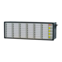
Explains front/rear view, LEDs, buttons, and terminal connections.
Monitoring and evaluation of system functions via LEDs and relay contacts.
Explains watchdog LED states and live-relay status.
Lists hexadecimal error codes and their meanings.
Defines operation modes (Horn muted, Unmanned) indicated by OK-LED.
Diagrams showing terminal assignments for various BSM models.
Details supply voltage, signal voltage, and power consumption.
Defines cascading functionality using DIP-switch S1 combinations.
Assigns DIP-switches to alarm groups and terminals.
Explains how relay groups are assigned and configured.
Lists default settings for LED colour, inputs, buttons, and relays.
Lists requirements for parameterisation software (OS, browser).
Instructions for installing the parameterisation software.
How to launch and log in to the parameterisation software.
Interface language can be changed between German and English.
Overview of the 5 submenus within the Parameter menu.
Defines the PC interface for parameterisation.
Provides diagnostics and displays current status of the annunciator.
Defines device type, adds/edits slave devices, exports/imports.
Defines Master-device type and adds/edits slave devices for cascading.
Options to store or load parameter files for the annunciator system.
Defines system functions like security and error masking.
Allows changing passwords for admin and user accounts.
Defines handling of device errors and which errors are displayed.
Parameterises fault annunciation functionalities for master/slave devices.
Defines device name, COM port, firmware, and signal channel parameters.
Parameterises reporting sequence (signalling, collective report, horn).
Assigns functions to push buttons and function inputs.
Defines assignment of 4 function relays to annunciation functions or buttons.
Configures optionally integrated repeat relays (inputs, inversion, output parallel).
Defines LED colours for operation indication and fault annunciation.
Overview of the 7 submenus within the Configuration menu.
Imports parameters for alarm channels and IEC objects from EES_Input tab.
Defines parameters for alarms like index, device number, signal name, and selective functions.
Configures IEC objects for reporting channels, including discrete parameters and object types.
Imports parameters for repeat relays and IEC objects from EES_Relay tab.
Defines parameters for repeat relays like input, pulse length, and selective functions.
Configures IEC objects for repeat relays, including discrete parameters and object types.
| Brand | EES |
|---|---|
| Model | BSM |
| Category | Touch Panel |
| Language | English |