Parameterisation
Page 28 of 45 MSM-BSM2G-BA-UK-001
6.2.3 Menu Device Administration
In the menu „Device administration“ the device type of the annunciator to be parameterised can be
defined. Additionally, slave devices can be added or edited and the parameterisation of the
annunciator(s) can be exported or imported.
6.2.3.1 Submenu New/Adapt
First the device type of the annunciator to be parameterised (Master-device) is defined. Choose the
respective device from the drop-down menu and select the checkbox „BSM/WAP-P“ for annunciators
of the type BSM-P.
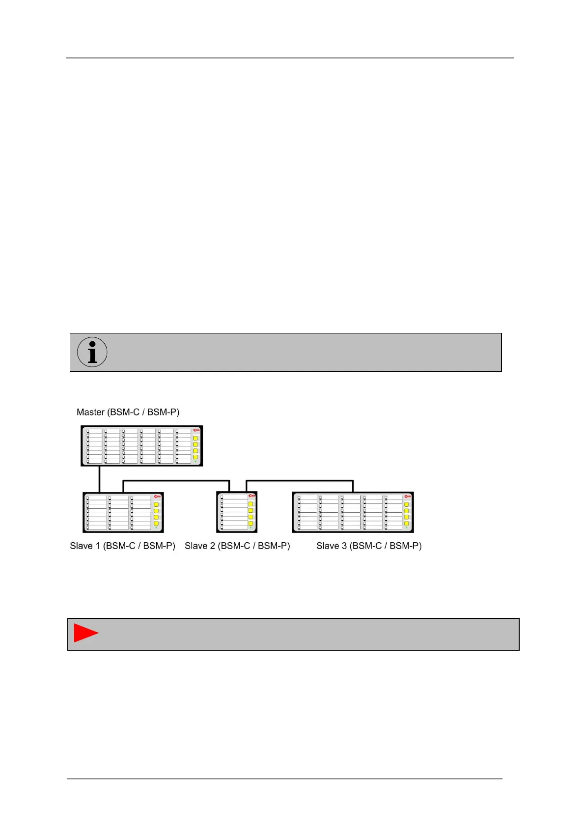
From a BSM or USM (Master) and up to 3 slaves (BSM-C or BSM-P) a cascaded annunciator system
can be formed providing one common alarm processing (Reporting sequence, forming of collective
reports and horn triggering). Through the protocol interface of the USM all alarms of the complete
system can be accessed.
The communication between the master and slave devices is realized through the integrated CAN-Bus
interface. The BSM or USM acts as “master” and the connected BSM-C or BSM-P act as “slave”. Thus
systems with up to 192 signal inputs (4*48) can be realized.
MSM-relay-modules cannot be connected to cascaded annunciators.
Fig. 6.8: Example of a cascaded annunciator system
Please note that the slave devices have to be set to slave-mode by DIP-Switch and the
respective slave addresses (1…3) have to be defined.
The parameterisation of cascaded annunciator systems is carried out in the Master
device (BSM-P or USM) and will be distributed automatically to the slave devices.