Configuration
MSM-USM2G-BA-UK-001 Page 21 of 45
5 Configuration
For both BSM-C and BSM-P some main settings of the annunciator can be defined by configuration
through DIP-switches. If further settings are required additional parameterisation by software is
possible for the BSM-P ( section “Parameterisation”).
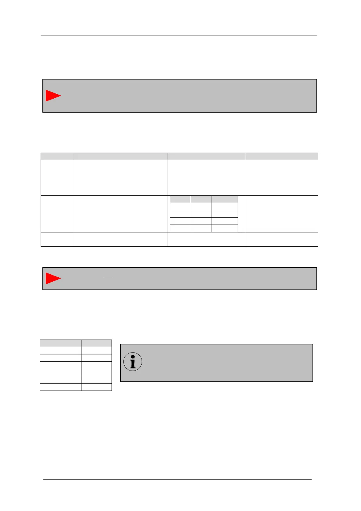
5.1 Cascading functionality (DIP-switch combination S1)
Table 5.1: Assignment of DIP-switch combination S1
5.2 Alarm group related DIP-switch combinations (S10 – S20)
The DIP-switches 1 and 2 of these DIP-switch combinations always affect the respective alarm group
(8 channels) which is assigned to the respective terminals.
Table 5.2: Assignment of the DIP-switch combinations to the alarm channels (input terminals)
Definition of the functionality as
per DIP-switch (configuration) or
parameterisation (this definition
is valid for all settings of the
annunciator)
OFF – Parameterisation
(software)
ON – Configuration
(DIP-switch)
S1/1 = OFF (device is Master)
- Number of connected slaves
or
S1/1 = ON (device is Slave)
- Slave-address
OFF, OFF
No connected slaves or
no slave address
If the BSM is not part of a cascaded annunciator system, DIP-switches S1/1 – S1/3 are to
be set to OFF (default setting).
To apply the DIP-switch settings to the annunciator, DIP-switch S1/4 has to be set to ON.
If the additional options of the software parameterisation are to be used for the BSM-P,
the DIP-switch S1/4 has to be set to OFF (default setting).
The functions of the switches 3 and 4 are set on one DIP-
switch combination for the whole device.
For the BSM08 this is the combination S10 and for all
other BSM it is the combination S12.