Parameterisation
MSM-USM2G-BA-UK-001 Page 27 of 45
6.2.1 Menu Serial Interface
Fig. 6.6: Dialog for selection of the parameterisation interface
In this menu the interface of the PC is defined, through which the connected annunciator will be
parameterised.
Please choose the respective interface (can be identified by the addition „VCP“ or through the device
manager of the PC).
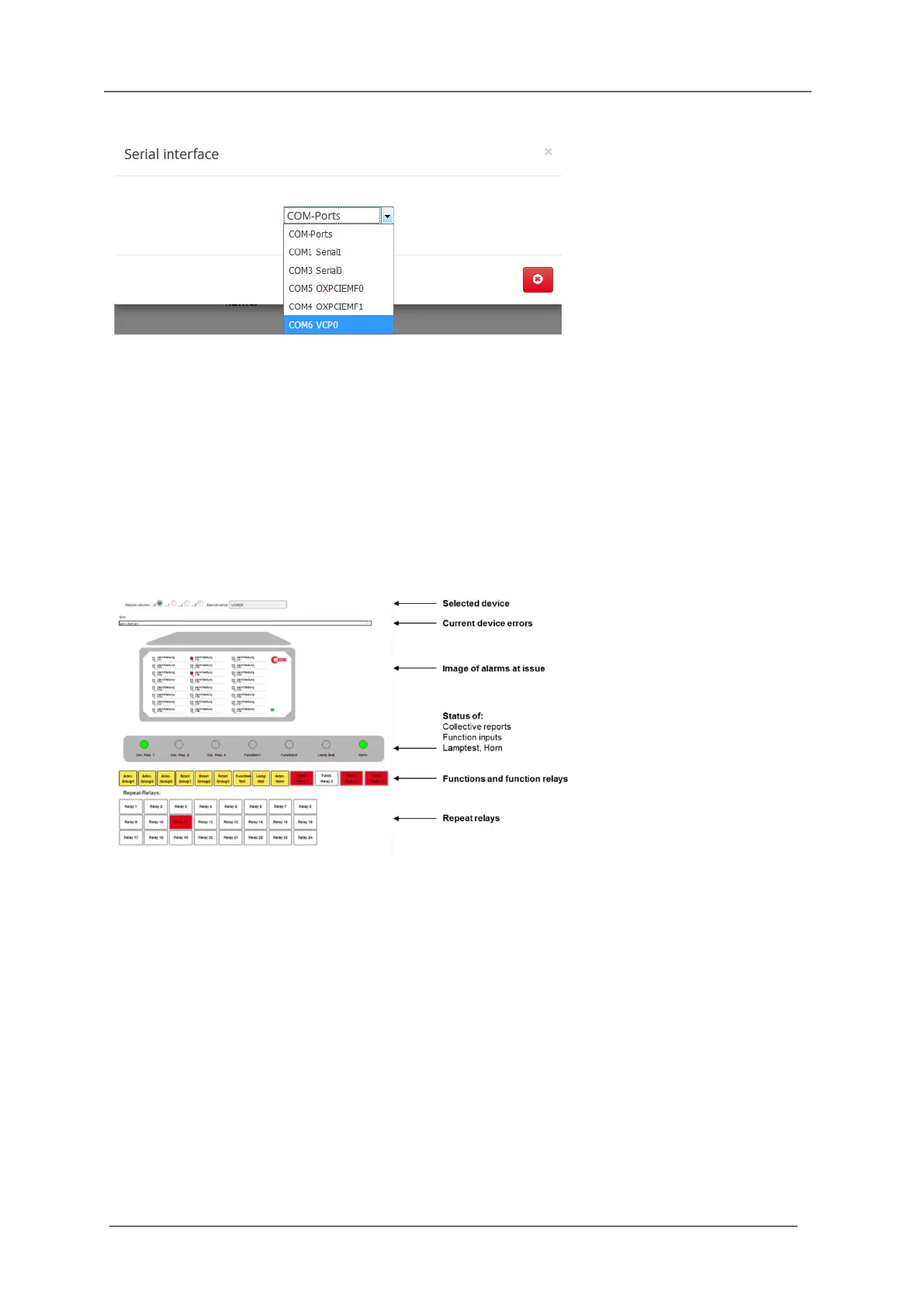
6.2.2 Menu Monitor
The page monitor offers diagnostics for the BSM. On this page the LEDs of the annunciator are
displayed with their current status (flashing, steady light, off).
Fig. 6.7: Monitor – a diagnosis tool
If the annunciator is used within a cascaded annunciator system, each of the devices can be displayed
in the monitor by click on the respective radio button „Annunciator 0…3“.
A slave device can only be chosen here, if it has been defined in the menu „System/Device
administration“ before.
The symbolically depicted yellow push buttons can be “activated” by mouse click and the
corresponding function is issued (acknowledgement, function test …).
The 4 function relays and – if available – the integrated repeat relays are depicted as well (red =
activated, white = non-operated state).