Functional description
MSM-USM2G-BA-UK-001 Page 13 of 45
3.6 Monitoring LEDs, buttons and connections
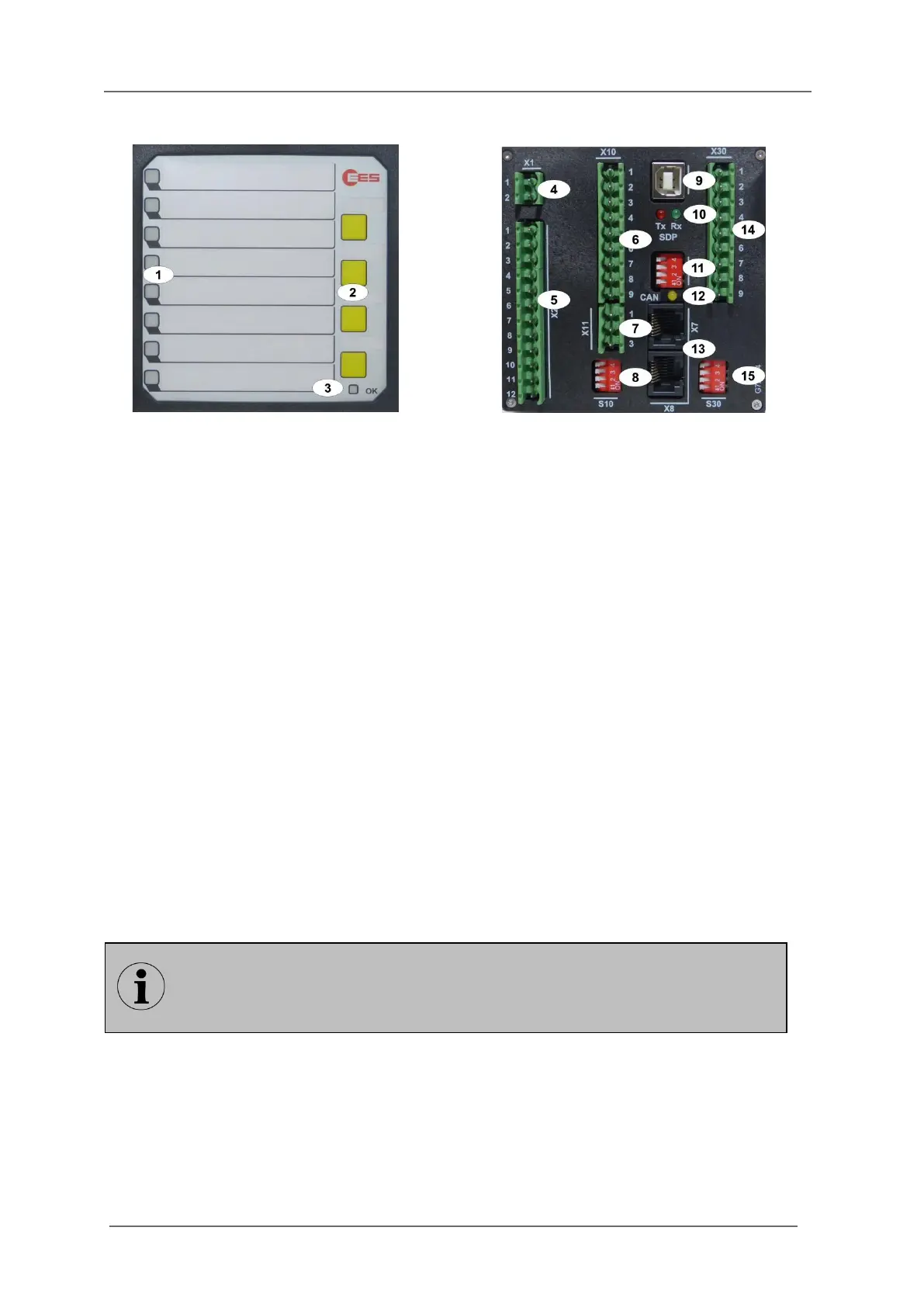
Fig. 3.4: Front- and rear view of the BSM08
[1] Alarm LEDs (function depending on reporting sequence)
[2] Buttons 1 … 4, (function depending on reporting sequence and parameterisation)
[3] Watchdog-LED „Self-monitoring“
Steady light green - no error
Off - no power supply or device defective
Flashing red - error ( section „Diagnosis“)
Flashing green - initialisation of the annunciator or activated operation mode
[4] Terminals power supply
[5] Terminals function relays
[6] Terminals signal inputs
[7] Terminals function inputs
[8] DIP-switch S10 (DIP-switch for alarm group functions)
[9] Service- and diagnosis interface USB-B*
[10] Watchdog-LEDs for service- and diagnosis interface*
red - Tx service- and diagnosis interface
green - Rx service- and diagnosis interface
[11] DIP-Switch S1 (cascading)
[12] Monitoring-LED CAN-Bus (yellow)
[13] 2 x CAN-Bus interface (RJ45)
[14] Terminals repeat relays**
[15] DIP-switches for the repeat relays – have no function in these annunciator variants**
* Only for BSM-P
** Only when optional integrated repeat relays are provided
In this section, the BSM-P with 8 alarm channels and integrated repeat relays is
used to illustrate the general setup of a BSM. The number of signal inputs and the
colours of the alarm LEDs can deviate depending on the configuration and size of
the respective BSM.