Mounting and installation
Page 20 of 45 MSM-BSM2G-BA-UK-001
4 Mounting and installation
1. Unpack all modules of the delivery and check for possible transport damages. Report any
transport damages to the responsible forwarding agent immediately. Please verify the integrity
of the delivery according to the shipping documents.
2.
Insert the annunciator into the prepared panel cut-out and fix it with the fasteners at the side of
the device.
3.
Connect the in- and outputs of the annunciator.
4. For a cascaded annunciator system, connect slaves according to steps 2 and 3 and connect
the cascaded annunciators to each other by means of a patch cable through the CAN-Bus-
interfaces (terminals X7 / X8 at the BSM and terminal X7 at the USM).
5. Connect the power supply and activate power supply.
6. Parameterise the fault annunciator (refer to sections “Configuration” and
“Parameterisation”).
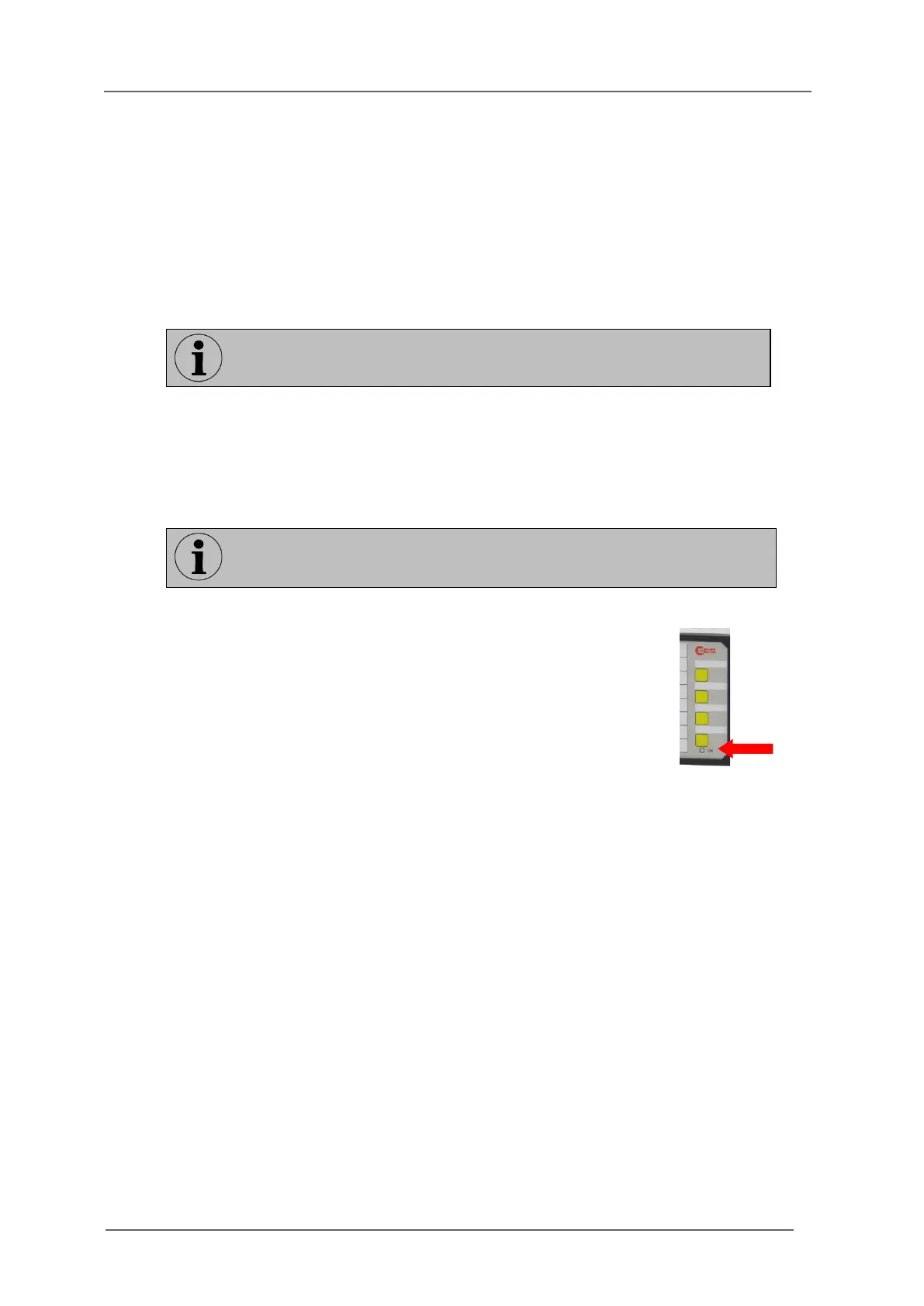
7. Watchdog-LED “Self-monitoring” is in steady light – the fault annunciator
is operational.
Watchdog-LED is flashing section “Diagnosis”.
The length of the wires of the in- and outputs should not exceed 3 m.
The length of the power supply wires should not exceed 10 m.