Parameterisation
MSM-USM2G-BA-UK-001 Page 31 of 45
6.2.3 Menu System
In this menu different system functions can be defined for the annunciator.
6.2.3.1 Submenu Security
The passwords for the two users “admin” (with authentication) and “user” can be changed here.
admin - administrator (rights for reading and writing)
user - user with limited rights (rights for reading only)
The password may consist of ASCII characters and is limited to a maximum length of 40 characters.
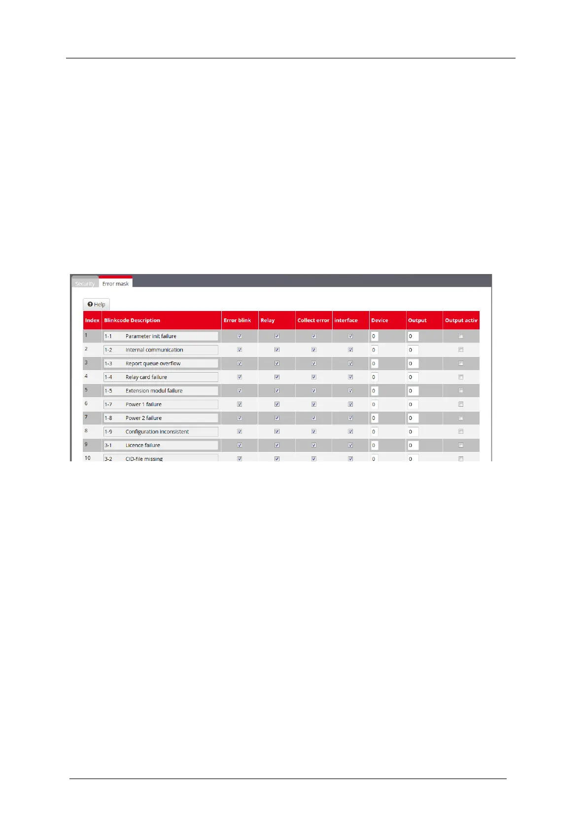
6.2.3.2 Submenu Error Mask
Fig. 6.12: Submenu Error mask
In this menu the handling of device errors of the BSM can be defined.
Blinkcode and Description
The entries in this field cannot be edited and show the blinkcode and the corresponding error in clear
text.
The first 20 entries are device errors and can be displayed with blinkcode by the Watchdog-LED „Self-
monitoring“. For example error „1-4 Relay card failure“ will be displayed with one long and four short
flashing pulses ( section 3.7 „Diagnosis“).
For the USM, the additional 32 error entries (160…191) signalise a faulty connection to an IEC104
client each and can only be forwarded to the IEC interface or be displayed on a signal channel.
Error blink
If this checkbox is activated the corresponding error will be displayed by flashing on the Watchdog-
LED.
Relay
The Alive-Relay is triggered by this error. (section 3.7 „Diagnosis“).
Collect error
This error is assigned to the collective device error which can be transmitted through the IEC interface
(only available for USM).