Functional description
Page 10 of 45 MSM-BSM2G-BA-UK-001
3 Functional description
3.1 Basic set-up of the BSM
The annunciators are available in 2 versions.
BSM-C: Basic version, configurable by DIP-switches
BSM-P: Software-parameterisable version
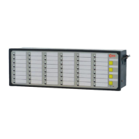
The fault annunciators are available with 8, 16, 24, 32, 40 or 48 signal inputs. The alarms are aligned
to groups of 8 inputs each on the device front. The closed front panel contains 4 push buttons, bi-
colour LED displays (red / green) and slide-in pockets for the labelling strips. The buttons have the
functions “horn acknowledement”, “alarm acknowledgement” and “lamp test” for the BSM-C and are
parameterisable for the BSM-P.
Two function inputs are available and can be used according to the chosen reporting sequence (e.g.
for external acknowledgement).
The annunciator features four change-over relays as integrated function relays. Alarm specific
functions (e.g. collective report or external horn triggering) as well as signalization of any malfunction
through a live-contact can be realized with the function relays.
All annunciators of the series BSM feature status retention upon power failure. This means that after
restoration of the supply voltage, the alarm status as of the moment of power failure is retained.
To forward single alarms input- or output parallel to a relay contact, two different methods can be
used:
1. Integration of additional relay cards (8 NO contacts each) as repeat relays. The assignment of
inputs to repeat relays can be done individually for BSM-P annunciators. The integrated
repeat relays are available as an option and have to be considered when ordering the device.
2. Connection of external relay modules through the CAN-Bus interface. For further details to the
relay extension modules, please refer to the separate datasheet MSM-EM-DB-UK.
All BSM fault annunciators provide a hardware-watchdog and software-monitoring. The fault-free
operation is indicated by an OK-LED and through a relay contact (live-contact).
Fault annunciators of the type BSM-P feature an internal horn (deactivated in default settings).
Additionally, an external horn can be triggered through a function relay.
The parameterisation of the BSM-P is done through the USB-parameterisation interface by means of a
parameterisation software. By these means the reporting sequence, input processing, assignment to
collective reports and horn triggering can be defined and protocol parameters, IP-address and
information object addresses can be parameterized. A detailed descripition of the parameterization
can be found in the section “Parameterisation”. Customised special reporting sequences can be
realized ex factory upon request.
The fault annunciator BSM provides USB and CAN-Bus interfaces, which will be described regarding
functionality and usage in the following sections.
Additional explanations to the integrated alarm sequeces can be found in the
separate document „Alarm sequences of EES-Fault annunciators“ (SM-MA-ZI-UK).
(Dokumentenname SM-MA-ZI-DE).