EFKA FP220A5911
62
11.14.4 Potentiometer Adjustment on JUKI Machine Model LU-2210/LU2260
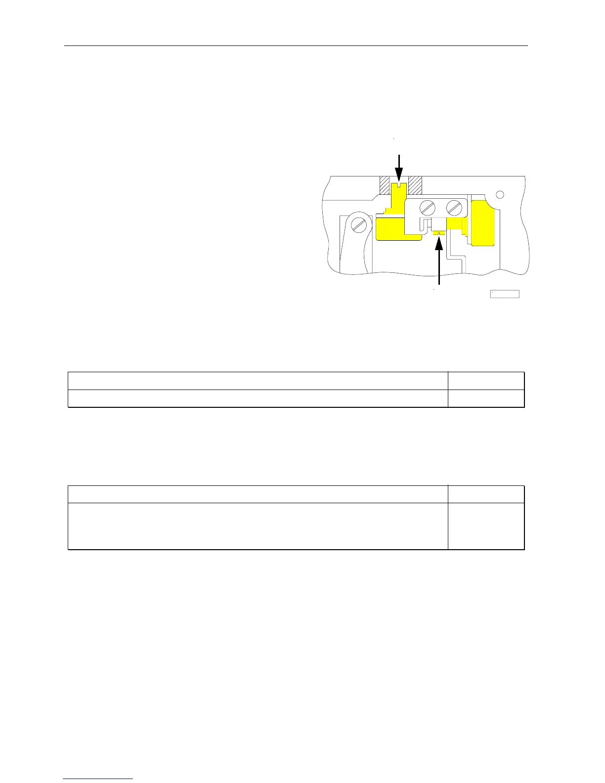
1. Set potentiometer (A) in the machine head, which is accessible by a bore at the rear, to the left endstop.
2. Turn the handwheel to position 1 for the speed depending on high lift (minimum high lift).
3. Set parameter 126 to 3 (activation of external potentiometer for the speed depending on high lift).
4. Select parameter 188. The V820 control panel display shows e. g. 3000 05 08 18
5. Press theF1 key, and the display shows e. g. Poti 185
6. The display value should be between 170 and 200.
7. Is this the case, the adjustment is completed. Proceed with point 10.
8. Should the value be outside of the limits, there would be an audible signal.
9. Loosen the 4 screws on the machine head and remove
the cover with the setting knob. Loosen adjusting screw
(B) and turn the potentiometer shaft to set the value
between the above limits. Then the audible signal will
be switched off.
10. Press the F1 key. The displayed value is taken over, and
a short audible signal will be issued.
11. If the display shows EEEE, turn the potentiometer (A)
in the machine head, which is accessible by a bore at the
rear, to the right so that EEEE goes off, and level 1
(maximum speed) is displayed.
View of the machine head with open cover
11.15 Speed Limitation n9
Function with or without control panel Parameter
Speed limitation n9 (n9) 122
If parameters 240...249 = 23, a speed limitation n9 will be switched on upon pressing an external key.
11.16 Speed Limitation n11 with Signal Output M10 / Flip-Flop 2
Function with or without control panel Parameter
Speed limitation n11 (n11) 123
Disabling of flip-flop functions at the seam end On/Off (FFm) 183
Function “speed limitation n11” inverted/non-inverted (FFi) 186
Function of signal M10 on socket ST2/29 after “power on” (FFo) 187
The speed limitation can be switched on by pressing a key on any of the inputs in1...i10 and switched off by pressing the
key again. A signal output which can be programmed individually (inverted/non-inverted) is provided for the speed
limitation. Furthermore, the function of signal output M10 can be determined after “power on”.
Settings necessary for speed limitation n11
!
Assign the function "speed limitation n11" to the key by means of one of the parameters 240...249 = 22. This function
has a flip-flop effect.
! Determine by means of parameter 186 whether signal M10 for speed limitation n11 shall be inverted or non inverted.
Parameter 186 = 0 Speed limitation n11 On/Signal M10 On or Speed limitation n11 Off/Signal M10 Off.
Parameter 186 = 1 Speed limitation n11 Off/Signal M10 On or Speed limitation n11 On/Signal M10 Off.
! Determine by means of parameter 187 whether signal M10 shall be issued at socket ST2/29 after “power on”.
Parameter 187 = 0 Signal M10 not active after "power on"; speed limitation n11 according to setting of parameter
186 (inverted/non-inverted)
Parameter 187 = 1 Signal M10 active after "power on"; speed limitation n11 according to setting of parameter 186
(inverted/non-inverted)
A
B
KL2473