EFKA FP220A5911
42
10.8 Positions
Function with or without control panel Parameter
Selection according to position sensor (PGm) 270
Number of angular degrees from the sensor position to position 2 (PGr) 271
Transmission ratio between motor shaft and machine shaft (trr) 272
After setting parameter 270 at “1, 2, 3 or 4“ an angular degree must be selected by means of parameter 271, which
determines the stop in position 2 or 1 after the sensor position. The transmission ratio must already have been input by
means of parameter 272.
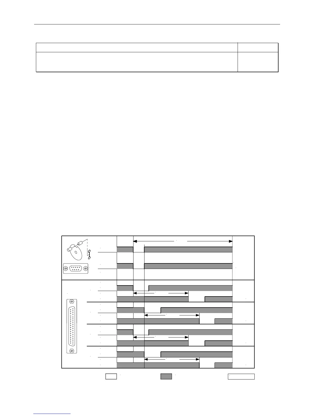
Connection of a sensor e. g. light barrier to socket B18/7. The following settings are possible using parameter 270:
Parameter 270 = 0 - The positions can be generated with the help of the transmitter incorporated in the motor and can be
set by means of parameter 171.
Parameter 270 = 1 - Setting the sensor to position 2.
- Position 1 is set according to the angular degree setting by means of parameter 271.
- Start measuring from leading edge position 2.
- 0V at input B18/7 (inside of the window)
- +5V at input B18/7 (outside of the window)
Parameter 270 = 2 - Setting the sensor to position 2.
- Position 1 is set according to the angular degree setting by means of parameter 271.
- Start measuring from trailing edge position 2.
- Input and output level as with setting “1“
Parameter 270 = 3 - Setting the sensor to position 1.
- Position 2 is set according to the angular degree setting by means of parameter 271.
- Start measuring from leading edge position 1.
- Input and output level as with setting “1“
Parameter 270 = 4 - Setting the sensor to position 1.
- Position 2 is set according to the angular degree setting by means of parameter 271.
- Start measuring from trailing edge position 1.
- Input and output level as with setting “1“
Parameter 270 = 5 - There is no position sensor. The drive stops unpositioned. The thread trimmer is suppressed.
= 0V
OUT
OUT
OUT
OUT
ST2
IN
POS1
ST2/20
POS2
ST2/20
POS1
ST2/21
POS2
ST2/21
POS1
ST2/21
ST2/20
POS2
ST2/20
POS1
POS2
ST2/21
POS
B18/7
SEN
= high
0256/SEN- 1
Pa 271
Pa 271
Pa 271
Pa 271
360°
270 = 1270 = 3270 = 4 270 = 2
+5V
0V