21
6.3. Axis Control Card Settings
WARNING:
Do not apply this process while the robots have energy.
WARNING:
It is delivered to you with this operation in the factory setting. Do not change un-
less necessary.
WARNING:
It is delivered to you with this operation in the factory setting. Do not
change unless necessary.
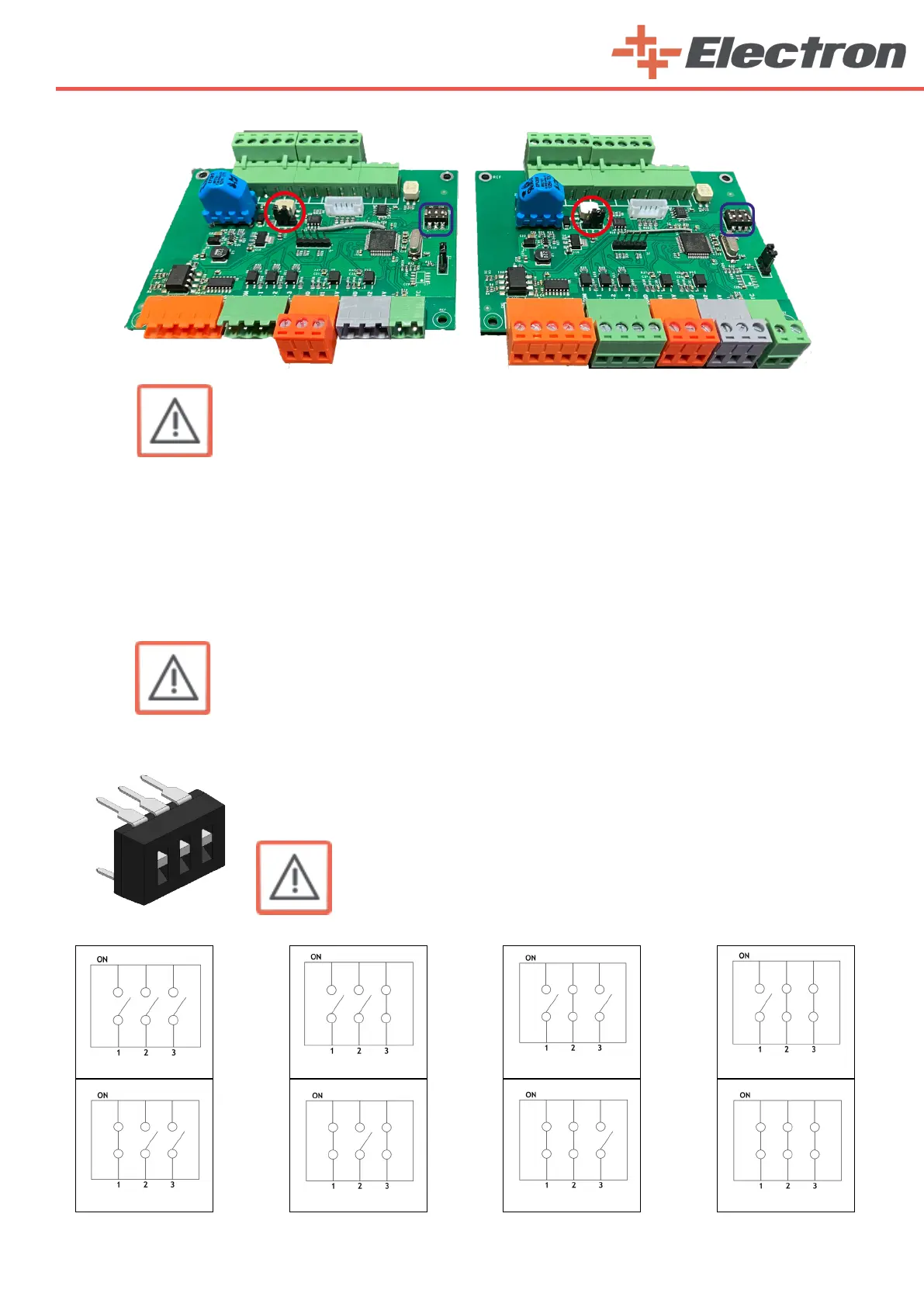
Make sure that the jumper marked with a red ring is attached correctly. Depending on how many
robots you have in your facility, the last one should be attached to pins 1 and 2. The last axis must be
attached to pins 2 and 3.
For example; You have 2 biaxial robots. It consists of 2 vertical and 2 horizontal axes. In this case,
you must place this jumper on pins 1 and 2 on the axis boards of the 1st vertical axis, 1st horizontal axis
and 2nd vertical axis.
The 2nd horizontal axis must be attached to pins 2 and 3.
The axis settings of the dip switch marked with a blue box on the axis card are
given below. Set the axis cards according to the axis order you are using. The reason
for giving 8 axes information is due to the ability of one E-Drive ZX02-E robot control
unit to control up to 8 axes.
4. Axis
8. Axis
3. Axis
7. Axis
1. Axis
5. Axis
6. Axis
2. Axis