-
-
You know that di
ital circuits produce low or hi
h
or H) outputs (0 or 1). Now you’re
oin
to create
logic tester that shows 1 for high level (H) and 0 fo
low level
L
on the LED display.
lide the switch to position B and construct th
circuit. When you finish the wirin
, slide the switch t
os
t
on
to turn on t
e
ower.
e num
er 0
s on
the display because the test terminal
terminal 13
is
t low level when no in
ut is exerted. Attach the tes
terminal-to-terminal 122 to apply +4.5V. The display
lters to 1
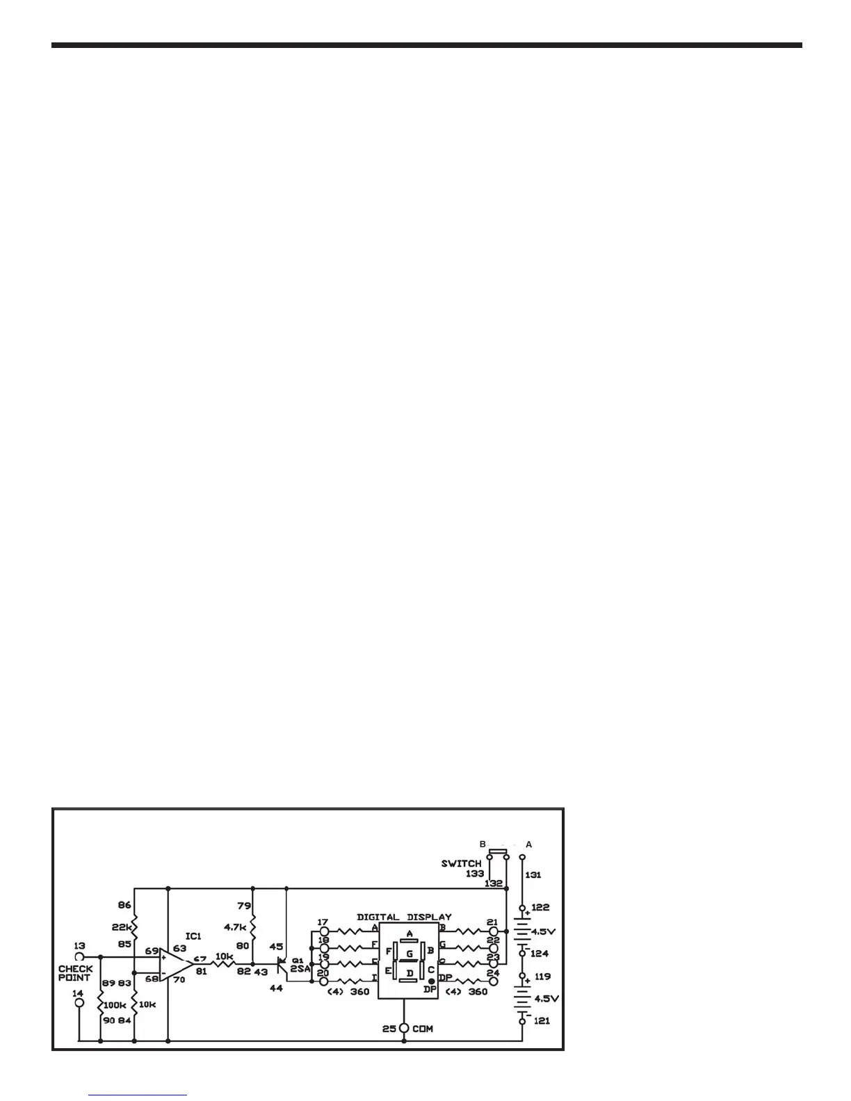
View the schematic. The operational ampli
ier work
s a comparator. The 22kΩ
nd 10kΩ resistor
produce a reference volta
e of 3V at its ne
ative (-
nput terminal. When the volta
e at its positive (+
terminal exceeds this re
erence voltage, th
comparator’s output level
oes hi
h, turnin
o
transistor
1. Now se
ments A, D, E, and F on the
display turn o
, leaving a 1 on the display.
otes:
EXPERIMENT #
4: L
I
TE
TIN
IR
IT
Wiring
equence
7-
-
-
-
-7
-
-21-2
-4
-1
4
-
-
7-
1
68-83-8
11
-124
122-1
1
69-89-13-CHECK POINT
121-25-70-90-84-14-CHECK POIN
Schematic