-
-
This circuit is a delayed timer that uses a
o
erational am
lifier and the RC time constant. R
tands for resistor/capacitor. A circuit that delays a
operation is a time constant
Throu
h resistors RA and RB the ne
ative
–
terminal of the o
erational am
lifier receives
volta
e of about 4.5V. This is the comparator’
reference voltage. Connected to capacitor C1 is th
ositive
+
terminal of the com
arator. This ca
acito
receives its charge through the series resistance o
2 and the control. The char
in
speed is slowe
when the resistance is large, and
aster when th
resistance is small. This charging speed set the delay
time
or the timer circuit
Now turn the control
ully clockwise to position 10.
Set the switch to position A to turn on the power. LED
1 li
hts first; LED 2 li
hts about 5 to 7 seconds later
This 5 to 7 second time di
erence is the delay tim
that is set by the CR time constant
Now, turn o
the power, set the control
ully counter
clockwise to
osition 1, and see what ha
ens whe
you turn on t
e power aga
n.
2
g
ts
ater t
a
LED 1 again, but how many seconds later
otes
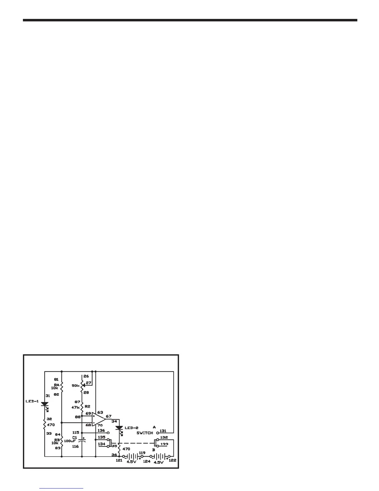
EXPERIMENT #
: R
DELAY TIMER
Schematic
Wirin
equence
1-
1-
-27-1
1
-
7
3-33-36-70-116-135-121
4-
7
-
2-
4
-
-
5-
-
22-132