A
ter you
inish the wirin
, set the switch to position B
LEDs 1 and 2 indicate the output voltage of th
operational amplifier I
. An LED li
hts if it is
onnecte
to 1.5
or
er.
n t
s exper
ment, w
onnect t
e two
s
n ser
es, so t
ey on
y
when connected with about 3V. When they are o
the output voltage o
the operational ampli
ier mus
e
ess t
an 3
ew t
e sc
emat
c
agram.
t
t
e sw
tc
a
position B, the 1.5V battery volta
e is connected to
resistors, with the positive terminal o
th
operational ampli
ier connected between th
resistors divide the 1.5
supply volta
e in hal
. This si
ni
ies the positive inpu
terminal receives an input volta
e o
only 0.75V
To total the output volta
e of the operational amplifie
you multiply its input voltage by the ampli
ication
factor (R1/R2) + 1. So, the output volta
e is 0.75V x
+ 1
= 2.4V
Slide the switch position A. This eliminates the 10k
resistors from the circuit, so the am
lifier’s
ositiv
input terminal receives the full 1.5V input voltage.
Usin
the above equation, you can see that th
output voltage o
the operational ampli
ier is no
1.5V x
220k
100k
+1
= 4.8V. Because the
volta
e supplied to them is more than 3V, the LED
li
ht dimly
Let’s alter the amplification factor.
lide the switch t
position B again and press the key. This adds the
47
res
stor to t
e 100
res
stor
n para
e
making total resistance of R2 about 32k
ow t
output voltage is 0.75V x ((220k
+1
= 5.9V
enou
h to li
ht the LEDs bri
htly
Now slide the switch to position A again
to connec
.5V to the amplifier’s positive
+
input terminal
, and
press the key. The LEDs light brightly. Calculating th
output volta
e
ives 1.5V x ((220k
2k
+1) =
11.8V. However, the actual output volta
e will b
limited by the available battery volta
e, which is 1.5
+ 3.0
+ 3.0
= 7.5
.
N
t
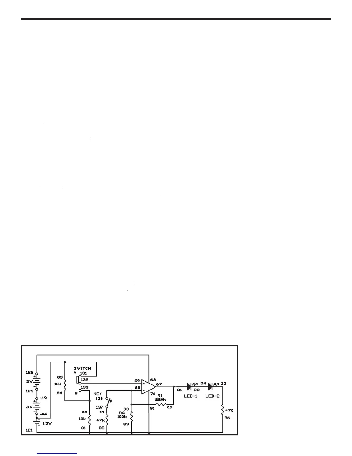
EXPERIMENT #71: CHANGING INPUT VOLTAG
iring Sequence
31-67-92
32-34
1-89-88-70-36-12
3-122
8-90-91-138
-
-
-
3-131-120
7-
7
-
-
-
Schematic