-
-
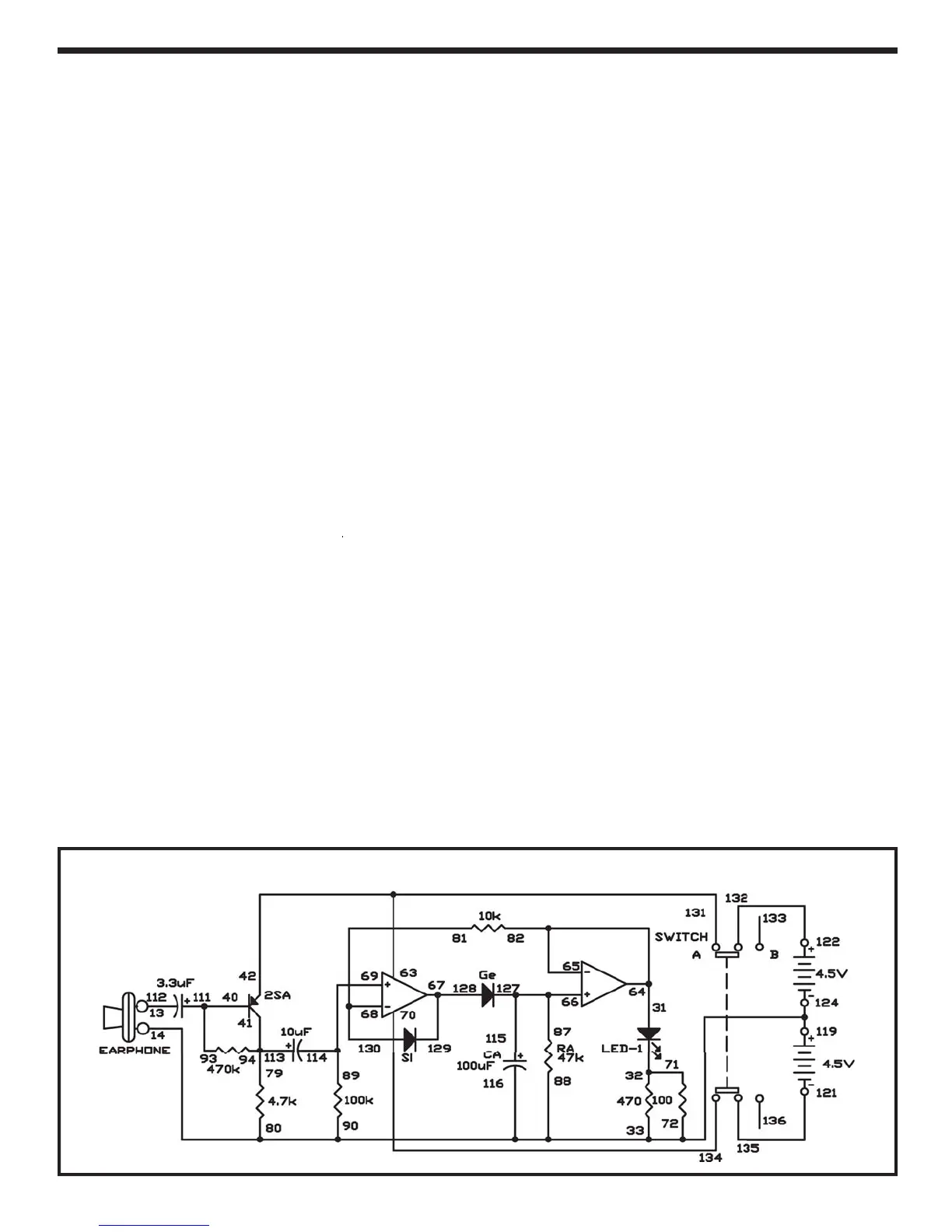
In this experiment, you will create a voice input powe
meter. The bri
htness of the LED in this circui
changes according to the level of voice input tha
comes from the microphone (the earphone).
ince
voice levels chan
e quickly, the bri
htness of the LE
should also adjust quickly. In order to show th
hi
hest voice input levels, we use a circuit called
pea
-
eve
o
c
rcu
t.
s a
ows t
e
to
o
certain brightness a
ter it reaches peak strength
rather than turnin
o
immediately.
Build the circuit, and set the switch to position A. Yo
will use the earphone as a microphone. Speak loudl
or blow strongly into the earphone. You can see th
LED
et bri
hter temporarily and then
radually
ro
imm
r
Study the schematic. You can see that the signal fro
the earphone travels throu
h the PNP transistor an
then becomes the positive
+
input for the firs
operational amplifier. The output level of the firs
o
erational am
lifier is stored in the 100mF ca
acitor
and slowly discharges through the 47k
esistor. The
gets
m as t
e vo
tage on t
e capac
to
decreases. The volta
e that li
hts the LED is also
e
back to the negative
-
input of the first operational
amplifier, where it is compared to the signal from the
earphone. I
the si
nal
rom the earphone is lar
er, i
c
arges t
e 100m
capac
tor; ot
erw
se t
ere
s no
output
rom it.
You can modify the brightness of the LED b
chan
in
resistor RA (47
Ω
or the ca
acitor C
10
F
t
:
EXPERIMENT #
7: V
I
E P
WER METER
Wirin
Sequence
12-1
-EARPH
N
1
-124-11
-
-
-
-
-72-14-EARPH
N
-
5-
-
32-71
-111-4
-
4-11
-4
-
-
87-66-127-11
7-12
-12
1-
-1
-
-
-1
21-1
-
Schemati